
As tempting as that is, there's still the problem of half a car taking up unavailable space in my driveway... If only I had a bigger driveway! Oh, or a massive warehouse to store cars in, that'd do too!
MickyG's MX-73 to 7M-GE Swap
- Thread starter mickyg
- Start date
You are using an out of date browser. It may not display this or other websites correctly.
You should upgrade or use an alternative browser.
You should upgrade or use an alternative browser.
Been trying to work that out myself. I also noticed the USB ports seem to be hidden!
Last edited:
Got the crank pulled tonight and am happy to report no other bearing issues other than slight copper coloured spots in places (bearings, not the crank). I'd still like to know what the copper stuff is - rust or minerals that end up looking like copper?
No obvious scoring or abnormal wear that I could see. And now that the crank's out, that rod journal on no6 doesn't look nearly as bad as I first thought. It'll still need some attention but the machining should be minimal.
I'll mic it all up sometime this week and take some pics as well - none tonight, straight business instead!
Of course, I knew that! Actually, I had no idea at all... I remember something in the TSRM about Kynton (or something similar) but had no idea of its composition.
Thanks for explaining that - now I know there's not some odd chemical reaction going on there!
Thanks for explaining that - now I know there's not some odd chemical reaction going on there!
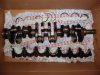
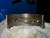
Pics.
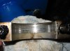
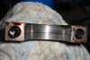
Crank and bearing wear up close. Number 1 was pretty worn and number 2 had that single score mark (no corresponding mark on the crank that I could see though). The rest were just like 2, only without the score mark. In my mind, this looks like normal wear. If any of you engine experts think otherwise, please let me know!
Crank and bearing wear up close. Number 1 was pretty worn and number 2 had that single score mark (no corresponding mark on the crank that I could see though). The rest were just like 2, only without the score mark. In my mind, this looks like normal wear. If any of you engine experts think otherwise, please let me know!
Attachments
Last edited:
Tonight:
Measured main journals and they're all marked 1 (Toyota stamp) except for number 6 (second to last), which is marked 2. The corresponding block/cap "cutouts" (for lack of a better term - if someone can tell me the real name, that'd be awesome) are all marked 2 except for 6, which is a 1. All bearings are 3s so it appears the right bearings are in there but I haven't looked at the manufacturer marking close enough to know if they're original or aftermarket.
As previously mentioned, no surprises yet. The mic measurements I did were pretty much what the tolerances in the TSRM said they should be.
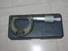
One question, how do you measure bearings that are concave when the most accurate micrometers are fairly large, flat contact patches? Do you end up having to use a Vernier style caliper gauge for that?
Measured main journals and they're all marked 1 (Toyota stamp) except for number 6 (second to last), which is marked 2. The corresponding block/cap "cutouts" (for lack of a better term - if someone can tell me the real name, that'd be awesome) are all marked 2 except for 6, which is a 1. All bearings are 3s so it appears the right bearings are in there but I haven't looked at the manufacturer marking close enough to know if they're original or aftermarket.
As previously mentioned, no surprises yet. The mic measurements I did were pretty much what the tolerances in the TSRM said they should be.
One question, how do you measure bearings that are concave when the most accurate micrometers are fairly large, flat contact patches? Do you end up having to use a Vernier style caliper gauge for that?
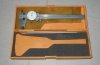
Snap gauge:

Hmmm... Looks a lot like my micrometer only bigger. It still looks like it'd suffer the same issues my existing micrometer would, in that the measuring contact areas (called "anvils" for the snap gauge) are wider than the curve of the bearing surface. I'm still not sure how you'd get an accurate measurement, unless the anvils were narrower. Am I way off?
Hmmm... Looks a lot like my micrometer only bigger. It still looks like it'd suffer the same issues my existing micrometer would, in that the measuring contact areas (called "anvils" for the snap gauge) are wider than the curve of the bearing surface. I'm still not sure how you'd get an accurate measurement, unless the anvils were narrower. Am I way off?
Oh, you mean for measuring the tunnels! I meant just for measuring bearing thickness. For that I'm guessing the caliper style guage is sufficient?
On second thought, it looks like there are attachments for the measuring anvils that give you narrower contact surfaces. Like these shown here
On second thought, it looks like there are attachments for the measuring anvils that give you narrower contact surfaces. Like these shown here
Last edited:
Micky: No use measuring the bearing thickness as it doesn't allow for crush.
You need to put the bearing pair in the tunnel torque to spec and measure it using an internal snap gauge.
You need to put the bearing pair in the tunnel torque to spec and measure it using an internal snap gauge.
I thought crush was what you got after the bearing/cap/crankshaft system had been in use for a while. If I'm understanding you correctly, it's just the amount of distortion you get when the ends of the bearings are pressed together in the tunnel. Very interesting.
I think all of this is sounding somewhat moot though, because if you measure the tunnel and the crank journal, and get the correct sized bearings for the proper oil clearance, it'll be right, right?")
I think all of this is sounding somewhat moot though, because if you measure the tunnel and the crank journal, and get the correct sized bearings for the proper oil clearance, it'll be right, right?
Today:
Got a bit done on the head. Pulled everything off, got all the valves out and measured head warpage (as well as can be expected before absolutely all traces of gasket are off. Also measured cam to shim clearance, which is again possibly moot as the valves were really dirty and probably weren't closing all the way.
I've been needing to put down various measurements and here's as good a place as any. All you who get bored with numbers (and I'm one of 'em), just ignore this bit.
Previous measurements for Crank (taken last week):
Main Journal 1:
Main Journal 2:
Main Journal 3:
Main Journal 4:
Main Journal 5:
Main Journal 6:
Main Journal 7:
So all are pretty much the same except 6 and from my measurements, what's stamped doesn't look like reality.
At any rate, all bearings are marked 3 and fit what the TSRM recommends.
Cam Clearances:
Exhaust Side:
no 1
no 2
no 3
no 4
no 5
no 6
Intake Side:
no 1
no 2
no 3
no 4
no 5
no 6
I noticed all valve faces and seats were in really good shape, except for the carbon buildup. There wasn't any pitting that I could see and the machining marks on the surfaces were still visible. All in all, way better shape than my 5m when I did the valves about 2 years ago.
What blew me away though was how much carbon buildup there was in the exhaust ports. When I got the valves out, I immediately knew why! The valve seals were completely gone. there was no rubber left on most of them and in some cases, the little retainer springs were even missing! This thing must have used as much oil as petrol!
Pics later...
Got a bit done on the head. Pulled everything off, got all the valves out and measured head warpage (as well as can be expected before absolutely all traces of gasket are off. Also measured cam to shim clearance, which is again possibly moot as the valves were really dirty and probably weren't closing all the way.
I've been needing to put down various measurements and here's as good a place as any. All you who get bored with numbers (and I'm one of 'em), just ignore this bit.
Previous measurements for Crank (taken last week):
Main Journal 1:
- 2.362"
- Crank Marking "1"
- Block (Tunnel) "2"
Main Journal 2:
- 2.361"
- Crank Marking "1"
- Block (Tunnel) "2"
Main Journal 3:
- 2.362"
- Crank Marking "1"
- Block (Tunnel) "2"
Main Journal 4:
- 2.364"
- Crank Marking "1"
- Block (Tunnel) "2"
Main Journal 5:
- 2.361"
- Crank Marking "1"
- Block (Tunnel) "2"
Main Journal 6:
- 2.362"
- Crank Marking "2"
- Block (Tunnel) "1"
Main Journal 7:
- 2.362"
- Crank Marking "1"
- Block (Tunnel) "2"
So all are pretty much the same except 6 and from my measurements, what's stamped doesn't look like reality.
At any rate, all bearings are marked 3 and fit what the TSRM recommends.
Cam Clearances:
Exhaust Side:
no 1
- .29mm
- .28mm
no 2
- .33mm
- .31mm
no 3
- .40mm
- .35mm
no 4
- .43mm
- .34mm
no 5
- .33mm
- .34mm
no 6
- .33mm
- .31mm
Intake Side:
no 1
- .20mm
- .20mm
no 2
- .23mm
- .25mm
no 3
- .31mm
- .33mm
no 4
- .28mm
- .26mm
no 5
- .28mm
- .24mm
no 6
- .28mm
- .26mm
I noticed all valve faces and seats were in really good shape, except for the carbon buildup. There wasn't any pitting that I could see and the machining marks on the surfaces were still visible. All in all, way better shape than my 5m when I did the valves about 2 years ago.
What blew me away though was how much carbon buildup there was in the exhaust ports. When I got the valves out, I immediately knew why! The valve seals were completely gone. there was no rubber left on most of them and in some cases, the little retainer springs were even missing! This thing must have used as much oil as petrol!
Pics later...
A few loose Valves but no real tight ones so the seats should all be ok and no sunken/recessed valves!
My thoughts exactly - based on the condition of the valves/seats, it's looking like this motor has relatively few miles on it. I'm sure it was running like an absolute pig when it was pulled though! No idea what seals the prev owner used but if I find out, I'll be sure to give them the widest berth I can!