3P's TCCS Disassembly/Analysis

bk_

New Member
Dec 5, 2010
34
0
0
Perth
1jzmerc.com
I think I found the OBD-like code section in the 1JZ-GTE rom image.

Points of interest:
* Starts @ 0xF047.
* Array of function pointers (jump addresses) @ 0xF0DA, length 10, 16-bit wide.

Apart from that... I could be totally wrong!
 

JonS

New Member
Apr 9, 2009
25
0
1
Cambridge
bk_;1702781 said:
I think I found the OBD-like code section in the 1JZ-GTE rom image.
Points of interest:
* Starts @ 0xF047.
* Array of function pointers (jump addresses) @ 0xF0DA, length 10, 16-bit wide.

It could also be the code that handles the results from reading the ADC. Normally there's a another table (0xF0CA?) near by with the sequence of ADC 'channels' to read.
 
Oct 11, 2005
3,816
16
38
Thousand Oaks, CA
If it looks like this, it is probably the ADC interrupt handler. Similar coding is used for injector programming.

Code:
ld	y, #0F896h	; load table base for channel jump address
		and	a, #00000111b	; isolate previous ADC channel 0 <= a <= 7
		shl	a		; x2 since 16 bit table
		add	y, a		; compute table	index
		ld	y, y + 00h	; load jump address into y for selected	ADC channel
		ld	d, ASR0N	; ASR0 neg edge	counter	value MSB
		sub	d, ASR0P	; compute ASR0 pulse width from	ADC of previous	channel
					; in d (units of 0.5us)
		sub	d, #0004h	; subtract constant from computed pulse	width
		bcc	loc_F88C
		clr	a		; clamp	to zero	if result negative
		clr	b

loc_F88C:				; CODE XREF: IV5_ADC+3Bj
		shl	d		; multiply pulse width by 2
					; units	now 0.25us
		jsr	ClampRegd	; Note:	pushes callback	address	on stack and
					; uses next two	words as data to called	function
; ---------------------------------------------------------------------------
		.dw 0FFFh		; max pulse width allowed (12 bits)
		.dw 0008h		; min pulse width allowed
; ---------------------------------------------------------------------------
		jmp	y + 00h		; jump depending on channel number
; End of function IV5_ADC		; Calibrated value of ADC is in	rD (08h	<= ADC <= FFFh

; ---------------------------------------------------------------------------
;List of Jump addresses	for jmp	y + 00h
;ch0 FA23 (Unknown analog sensor next to VTA and under KS)
;ch1 FA54 (B+)
;ch2 FA9D (THA)
;ch3 FA17  straight to RAM
;ch4 FB0C (THW)
;ch5 F8B1 (TPS)
;ch6 FB2E  N/U
;ch7 FA1D  straight to RAM

;table of addresses for	each channel ADC routine
MAP_F896:	.dw 0FA23h		; ch0: FA23h
		.dw 0FA54h		; ch1: FA54h
		.dw 0FA9Dh		; ch2: FA9Dh
		.dw 0FA17h		; ch3: FA17h
		.dw 0FB0Ch		; ch4: FB0Ch
		.dw 0F8B1h		; ch5: F8B1h
		.dw 0FB2Eh		; ch6: FB2Eh
		.dw 0FA1Dh		; ch7: FA1D
;------------------------------------------------
;ADC channel command table
ADC_CHCMD:	.db  40h ; @		; ch0
		.db  44h ; D		; ch4
		.db  40h ; @		; ch0
		.db  42h ; B		; ch2
		.db  40h ; @		; ch0
		.db  44h ; D		; ch4
		.db  40h ; @		; ch0
		.db  41h ; A		; ch1
		.db  47h ; G		; ch7
		.db  43h ; C		; ch3
		.db  45h ; E		; ch5
;------------------------------------------------
 
Last edited:

bk_

New Member
Dec 5, 2010
34
0
0
Perth
1jzmerc.com
woops. my bad.

I'm trying to get my head around the instructions but getting confused too much. I've used as much as possible information provided by M68HC11 reference manual (mostly the same instructions but totally different op codes) but still am stuck (or not 100% sure) about some instructions.

Could you clarify the following individual instructions?
Code:
st    a, [y]
xch   a, b
cmpb  a, #0x08
subc  a, #0x00
mov   d, x

Thanks.
 
Oct 11, 2005
3,816
16
38
Thousand Oaks, CA
st a, [y] stores the data in register A to the RAM location pointed to by register Y . The pointer in Y is automatically incremented afterwards.
xch a,b exchanges the contents of register A and B.
cmpb a, #0x08 does a binary compare of each bit in register A with the corresponding bit in the immediate data 0x08
subc a, #0x00 does a subtract with carry from register A with the immediate data A-0x00 in this case.
move d, x moves the data in register D to register X. These are both 16 bit registers.

Kashi has a document that lists all of the instructions. Unfortunately he charges money for it.
 
Last edited:

bk_

New Member
Dec 5, 2010
34
0
0
Perth
1jzmerc.com
Cool. Thanks.

Couple of more questions in regards to the 8X MCU:
* Fractional division or integer division? Where is the result stored? and the remainder?
* Arithmetic shift or logical shift?
* What size (8 bits or 16 bits) argument is used by opcode 0x39 (st s, arg) and 0x3B (st y, arg)?
 
Oct 11, 2005
3,816
16
38
Thousand Oaks, CA
div d, #xx places quotient in B and remainder in A. Note that if A >= #xx then this is a NOP with carry = 1
there are a bunch of shifts. For example SHR is a logical shift and SHRA is an arithmetic right shift and RORC is a right rotation.
The argument for opcode 39h is 8 bits, it is essentially a zero page direct address. The stack pointer is 16 bits, and this processor is big endian but I think you already figured that out.

If anyone has a gray plug 7MGTE ecu to sell, let me know.
 

JonS

New Member
Apr 9, 2009
25
0
1
Cambridge
bk_;1705370 said:
I've written up a preliminary datasheet-like document describing the toshiba 8x MCU instruction set / opcodes.
Cool, that looks like a useful reference. I noticed a list of internal registers at the end, I can probably help out with that.
 

JonS

New Member
Apr 9, 2009
25
0
1
Cambridge
bk_;1702781 said:
I think I found the OBD-like code section in the 1JZ-GTE rom image.
I've now found the ODB code in the 3S ECU, it's in the D151803-9661 MCU. The stream is generated in software from a timer, pin PA4 (31) is the inverted stream, pin PA5 is an active-low enable signal.

There's a subroutine at 0xD0FF that fetches the next byte in the stream, a table at 0xD139 contains the sequence of memory addresses to use for the data. 0xD155 is the subroutine that generates the next bit in the stream, called from interrupt handler IVc.
 

JonS

New Member
Apr 9, 2009
25
0
1
Cambridge
bk_;1699871 said:
The order of the OBD data is as follows:
0) UNKNOWN 8 bits
1) INJ
2) IGN
3) IAC / ISCV (steps?)
4) RPM (*25 if under 2850 RPM?)
5) MAP (kPa)
6) ECT (V, 8 bits ADC)
7) TPS (%, /2?)
8) SPD (kph)
9) UNKNOWN 8 bits
10) UNKNOWN 8 bits
11) FLAGS #1
12) FLAGS #2
After looking at the 3S ODB code a bit more, it certainly looks like it follows the same order of ODB data. There are the same number of bytes and RPM, MAP are definately in the same place. FLAGS #1 & #2 could also be the same but I haven't worked out the bits in the flags yet.
 

bk_

New Member
Dec 5, 2010
34
0
0
Perth
1jzmerc.com
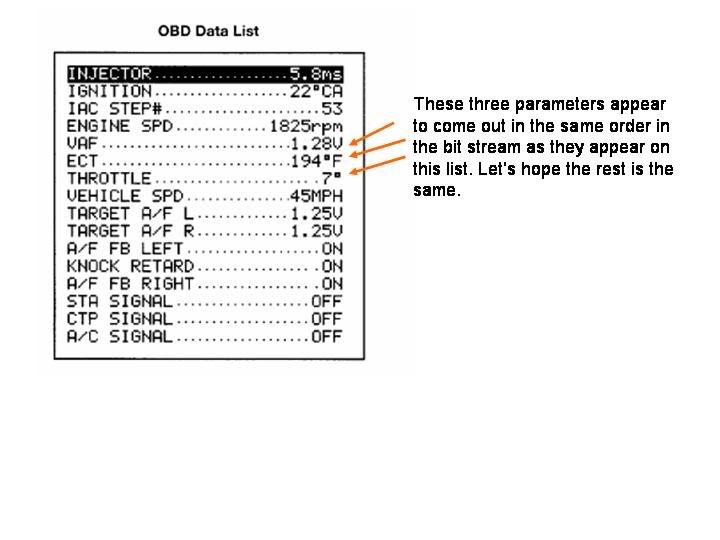
Here's an image from a toyota workshop manual that I used 4-5 years ago:
p1706970_1.jpg


I suspect #9 is NBo2 #1 voltage, and #10 is NBo2 #2 (eg: on V6 / V8 toyota engines) voltage.

Couple of notes on the JZX90 (6980) rom:
* OBD handler is at EEB1 / EECE.
* OBD list of addresses is at FBFE.
* UNKNOWN #10 read address is set to the address of WORD #13, which is 0x0000.

And in general:
* CTP: Closed Throttle Position.
* ECT: Engine Coolant Temperature.

According to the "screenshot" I posted, the following match up in the same order as I reverse engineered:
* WORD #12.0: STA switch
* WORD #12.1: CTP switch (1=throttle closed)
* WORD #12.2: A/C switch

Hope that helps.
 
Last edited:

bk_

New Member
Dec 5, 2010
34
0
0
Perth
1jzmerc.com
Here is another piece of reverse-engineered information (from OBD stream and toyota technical repair manual) in regards to ECT.

These numbers are approximate, so may be off by a few degrees or more, especially below 25C or above 90C. I do know based from my OBD reader that closed-loop is triggered at 71C or 72C (Vect=~0.68 or V8bit=~34).

(ECT=C+40), (ECT=C), voltage, voltage(8 bit value)
0, -40, 5.0 V, 255
20, -20, 4.3 V, 219
40, 0, 3.4 V, 173
60, 20, 2.4 V, 122
80, 40, 1.5 V, 76
100, 60, 0.9 V, 46
120, 80, 0.5 V, 25
140, 100, 0.3 V, 15
 

bk_

New Member
Dec 5, 2010
34
0
0
Perth
1jzmerc.com
SideWinderGX;1708049 said:
Is that ECT temp really the transmission?

I'm lost by what you mean. The value is sent as an 8 bit 5V ADC value. Whether it is converted to C or F, that's up to the OBD reader to do.

I'm happy to validate the voltage at 25C, 50C, 70C against the 1JZ-GTE PowerFC unit that I have. But it's low on my priority list.

"Easier" to find the actual lookup table in the OEM ECU. I've provided a good starting point. :)
 
Oct 11, 2005
3,816
16
38
Thousand Oaks, CA
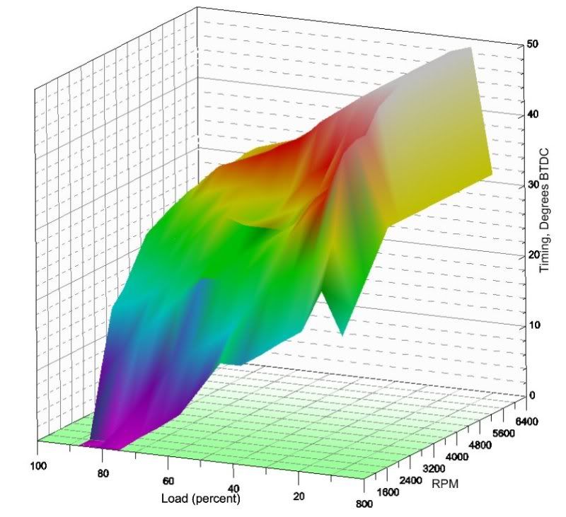
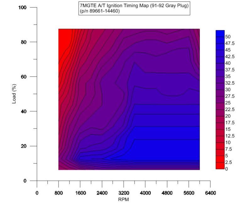
The ignition timing is pretty much understood now. I've been looking specifically at the 91-92 7MGTE A/T ECU, so these timing numbers may not match exactly for the M/T, but this is from the last firmware release for the 7M so should reflect Toyota's best data.

The timing is pulled from a table (plotted below), and corrected for a number of effects such as warmup (the warmup table mostly seems to advance, but for some load range retards, the timing up to about 60C, then is deactivated). There is a cranking advance that can add up to 9 degrees advance during a cold start. There is a hot coolant table that retards the timing for coolant above 95C, peaking out at 105C (max correction is 4 deg retarded). There is also a knock value that is subtracted from the timing. I datalogged all of these and they seem to behave as expected. I was surprised to see knock retard being applied while the warmup advance was in effect. The two were kind of fighting each other it seemed. Finally, the most interesting part was that there are timing adjustments computed for each cylinder, and these are only used at idle to stabilize the rpm. The idle rpm is compared to a running average, and if it is below average for a cylinder that cylinder will be advanced up to 3 degrees to compensate. Very clever, I bet no one else had this back in 1986. For idle, there is a simple map versus rpm that has a range of 12 to 22 degrees from 1000 to 2400 rpm (here idle is defined as the IDL switch being closed), outside that it is clamped at the end values. With A/C on, idle timing can be no less than 20 degrees, and for the A/T, when in gear idle timing is no less than 16 degrees.

Finally, for some conditions like cranking, rpm < 300, and diagnostic mode the timing calcs are bypassed and timing is set to 10 degrees.

The 2D timing map is plotted below. The ECU can adjust from 0 to 50 deg BTDC. This map is located at D4A1h if anyone is looking. It is a 14 x 14 map. RPM is mapped from 800 to 6000rpm. Outside that range values are clamped. Load is from 6% to 84%. I am using the load fuel cut value as 100%. The ECU linearly interpolates in 2 dimensions when the operating value does not land exactly on the mapped value.

p1712465_1.jpg


p1712465_2.jpg