
You're the second person to ask that! I know the docs say that it does that, but I cannot see it in the code. I am wondering if they didn't implement it with the ISCV instead. When I get to figuring out the idle code things should become clearer.
3P's TCCS Disassembly/Analysis
- Thread starter 3p141592654
- Start date
You are using an out of date browser. It may not display this or other websites correctly.
You should upgrade or use an alternative browser.
You should upgrade or use an alternative browser.
Since the manuals claim its done with timing and also support everything else you've found it should be in there. You can see and hear cross counting when off idle but not when on and as you know count rate is much slower at idle. I use it as a quick and dirty method of checking the O2 sensor.
Ah well, keep digging. You're further into it than I ever got...
Ah well, keep digging. You're further into it than I ever got...
I would think the idle rpm stabilization code that I did find would pretty much do the same thing. Its just looking for idle speed variation and making corrections to timing to compensate. Its definitely fast enough to correct for cross-counting, since its making change to the timing for the next cylinder to fire. I will datalog the corrections and the ox sensor cross counts and see if they line up.
I always knew the A70 was "bright for its age", but it's absolutely amazing how advanced this ECU was considering it's origin is the 1980's...
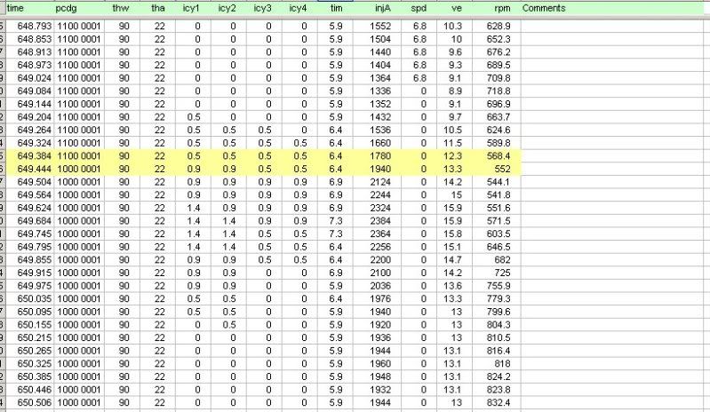
Here you can see the correction values for 4 of the 6 cylinders (icy1, icy2 icy3 icy4) and also the deglitched crosscount input (bit6 of pcdg). You can see that when the cross count happens (yellow highlight) the cylx variables come alive to stabilize the idle, then they simmer down after a second or so has passed. The peak correction here is 1.4 degrees.
Note that the indicated cross-count is delayed due to the deglitching algorithm, that's why the corrections seems to start before the x-count. Timing value (tim) logged does not have the 10deg base timing added, so the real value is 10+ the value you see in the column.
Note that the indicated cross-count is delayed due to the deglitching algorithm, that's why the corrections seems to start before the x-count. Timing value (tim) logged does not have the 10deg base timing added, so the real value is 10+ the value you see in the column.
I see that the minimum idle timing goes from 16deg to 20 deg when AC is on. I also see that there are two idle speed target values,depending on whether the AC is on or not. I don't understand the idle speed code very well, so can't say much more than that.
What are the units of the ignition table? 0.25?
What are the units of the load? airflow / map voltage? or is it converted to L/sec / kPa?
I was going to measure the ignition timing vs pressure but the hardware / software I thought would do it, is "limited" by the software. So that's now out of the question for me.
What are the units of the load? airflow / map voltage? or is it converted to L/sec / kPa?
I was going to measure the ignition timing vs pressure but the hardware / software I thought would do it, is "limited" by the software. So that's now out of the question for me.
The ignition table is in degrees BTDC. The load units are volumetric efficiency in percent. 100% equals fuel cut on a stock ECU. Since the table only goes to 88%, the remaining 12% just uses the nearest edge value.
For people using a LEX AFM, this map need to be compressed by ~25% to maintain the stock profile, and should have one or two rows added to take it out to 100%. That is something I can do with our extender board.
For people using a LEX AFM, this map need to be compressed by ~25% to maintain the stock profile, and should have one or two rows added to take it out to 100%. That is something I can do with our extender board.
What I meant was, what are the units in the ignition table of the ECU? because the raw ignition values go up to 200.
And are the load units in the same interval? In other words, how is it divided in the table?
And are the load units in the same interval? In other words, how is it divided in the table?
You are asking about the resolution then. Timing is a 16 bit value with a resolution of 30/256 = 0.12 degrees. It is clamped to a 50 degree range.
Load is a 16 bit value with a maximum of 0xC800. Anything over that is clamped and sets code 34.
Load is a 16 bit value with a maximum of 0xC800. Anything over that is clamped and sets code 34.
3p141592654;1713712 said:...
This map is located at D4A1h if anyone is looking. It is a 14 x 14 map. RPM is mapped from 800 to 6000rpm.
OK... let me try again
")
* RPM min: 800 (where / how is this represented by the MCU?)
* RPM max: 6000 (where / how is this clamp value defined? or is clamp value slightly higher and defined outside of the table?)
* RPM interval: 400 (where / how is this value derived?)
* IGN raw min: 0
* IGN raw max: 200 (divide by 4 to get IGN in degrees?)
* load min: ??? (how is this value derived?)
* load max: 84% of 0xC800 ? (Vadc value of AFM / MAP? 100 * X / 0xC800 = ~84 - where / how did you derive X?)
* load interval of table: ??? (clamped value divided by the number of rows?)
Sorry for being a pain in the ass. I'm more about trying to understand how / where the values are derived, rather than the values specific to the 7M-GTE.
The code is fairly complex, so there are not simple answers to these questions. RPM is computed by measuring the time between NE pulses. The average time is inverted and then scaled to fit into a 16 bit integer. The MSB of that number is used as the input for the RPM axis. The MSB value is divided by 8 before being used as the table index. This is where the 400 rpm steps comes from. There is a 2D interpolation subroutine that also takes two bytes that specify the origin of the table, (so that is where RPM min and VE min are defined). VE is similar, except it is scaled by 0xC. The max values are defined simply by when the table ends. The first two bytes of the table specify the max rows and columns of the map.
The timing routine calls a clamping subroutine that prevents its value from going outside 0 to 50 degrees. This clamping subroutine is used over and over to prevent variables exceeding desired ranges. For the7M, IGN raw max is 0x2AB (not 200), so I'm not sure where you are getting that from.
Unfortunately, since its all written in assembly language, the only way to really understand this stuff is to spend a lot of time decoding the code. If you like doing puzzles, then you'll enjoy figuring out the code because it is just one big puzzle at first.
Work always gets in the way around this time. I am working on the fuel code whenever I get a chance. It is the most complicated part of the ECU, but progress is being made.
3p141592654;1713633 said:For people using a LEX AFM, this map need to be compressed by ~25% to maintain the stock profile, and should have one or two rows added to take it out to 100%. That is something I can do with our extender board.
I was thinking about this also. Too much advance can hurt performance. And this is never talked about when the Lex upgrade is talked about.
Nick M;1721078 said:Too much advance can hurt performance.
Actually in my experience the advanced timing helps quite a bit performance wise with this mod. However, whether or not it's safe is another question entirely. Lexus AFM cars seem to be more prone to destructive detonation, and I suspect this is the cause.
Would be interesting to do a side by side test, one with the Lexus AFM and a second with it scaled properly, I suspect some of that "quick spool" the Lexus mod is so famous for would go away.
I know out west they don't get 93 and 94 octane. With the higher octane and too much advance, it can start to light while on the compression stroke. Any engine can do this if over advanced. And I don't know just how much is too much. My Lex meter and 550's went on the same time as the DrJonez manual controller went to 13 psi. So I didn't give it consideration for a quicker spool, but that makes sense.
The knock routines will compensate for the over-advanced timing, but the concern would be that you might get in a situation where it can't react fast enough. It has a very slow decay, so that any knock detected retards the timing for some time afterwards even if the knock has gone away. All of this complexity in the ignition management is likely why the Lex upgrade works at all.
3p141592654;1713316 said:I see that the minimum idle timing goes from 16deg to 20 deg when AC is on. I also see that there are two idle speed target values,depending on whether the AC is on or not. I don't understand the idle speed code very well, so can't say much more than that.
A/C idle speed also depends on shift solenoids. I can't find my table at this time, but I think it is in one of the older books, like 850. For example, A/C switch is on and you ar in park or neutral, and target speed is 900. But in drive it is 750, or something like that. The chart just shows solenoid on/off with A/C on/off and target speed. I just want to be sure you aren't missing anything. Maybe it was in the repair manual.