LSx coils
- Thread starter northwestsupra
- Start date
You are using an out of date browser. It may not display this or other websites correctly.
You should upgrade or use an alternative browser.
You should upgrade or use an alternative browser.
NashMan;1610104 said:not much fun for swaping starters or removeing trans
whenever was the starter fun
IJ.;1605377 said:
its all ordered and on its way "including tool"
tada, wires are made  fit great, ordered some MSD 2 wire seperators with some heat guard crap idk what that is but it was only 1 dollar more
  pictures. btw spark plug crimpers made life super easy. all wires come in at a round up of 25-30 ohms. had to order the coil ends also, didnt notice that it was just a quanity of 2 per order, so 2 more are on the way with the separators.
PICTURES!
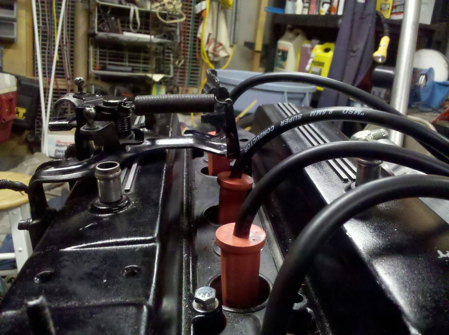
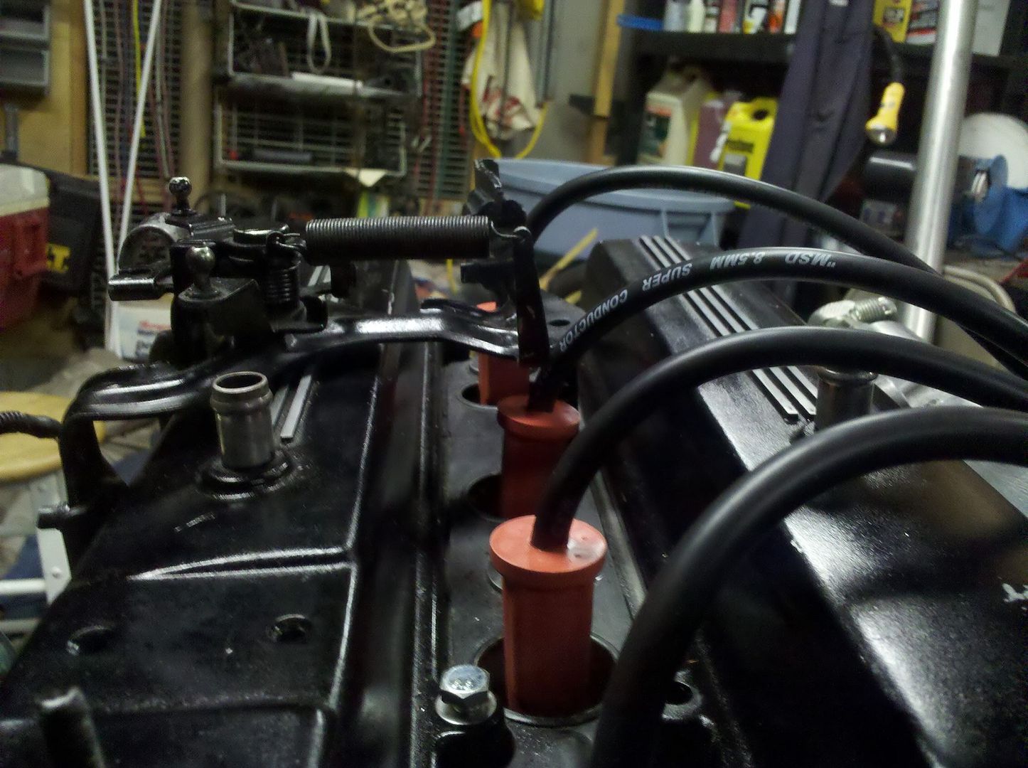
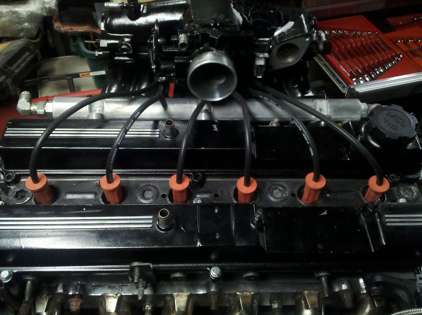
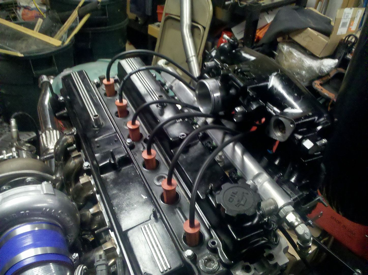
all of the plugs are very tight and kinda hard to clip onto the spark plugs and same with the coil ends. "or at least the 2 that i have on there now " i also put some High temp Orange permatex on the plug ends so the wires dont move when plugging them on and plus it will seal it even more than it already is "which was already sufficient"
PICTURES!


all of the plugs are very tight and kinda hard to clip onto the spark plugs and same with the coil ends. "or at least the 2 that i have on there now
Hi!
I was wondering if someone could help me out on this.. I have just bought a set of LS2 coils, and i want to wire them up so they will work with my AEM EMS 30-1130.. Do someone know how to wire these in? I need to run batch / wasted spark becuase the aem only has 5 coil inputs.. Right?
I was wondering if someone could help me out on this.. I have just bought a set of LS2 coils, and i want to wire them up so they will work with my AEM EMS 30-1130.. Do someone know how to wire these in? I need to run batch / wasted spark becuase the aem only has 5 coil inputs.. Right?
SupraMKIII-NO;1672772 said:Hi!
I was wondering if someone could help me out on this.. I have just bought a set of LS2 coils, and i want to wire them up so they will work with my AEM EMS 30-1130.. Do someone know how to wire these in? I need to run batch / wasted spark becuase the aem only has 5 coil inputs.. Right?
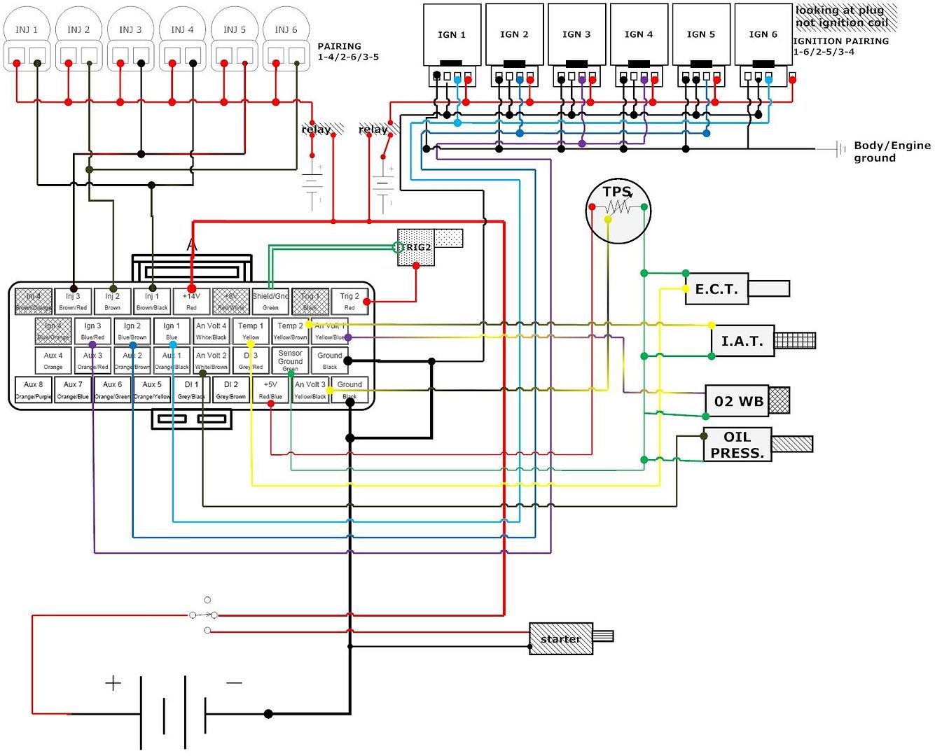
from what i know of yes, the AEM only has 5. i had posted the wiring diagram i think on page 2 if not there is a wiring diagram for ls2 coils on the megasquirt website. also keep in mind that the diagram for the ls2 wiring is looking at the coil "NOT THE PLUG"
Hi.
Yes i got the wiring diagram for the LS2 coils. But mine question is how to wire them in to the AEM EMS? As the aem only have 5 coil inputs, i do need to wire up the LS2 coils in pair? One trigger signal from the AEM needs to fire two coils at the same time.. Or am i wrong here?
I was thinking about wire the coils like you (northwestsupra) showed in you wiring diagram at page 8. I can use the same wiring with my AEM EMS, right? Just pair up two and two coils to one coil output on the AEM?
Last edited:
SupraMKIII-NO;1672975 said:Hi.
Yes i got the wiring diagram for the LS2 coils. But mine question is how to wire them in to the AEM EMS? As the aem only have 5 coil inputs, i do need to wire up the LS2 coils in pair? One trigger signal from the AEM needs to fire two coils at the same time.. Or am i wrong here?
I was thinking about wire the coils like you (northwestsupra) showed in you wiring diagram at page 8. I can use the same wiring with my AEM EMS, right? Just pair up two and two coils to one coil output on the AEM?
Yes wire it in pairs. But not shown in my diagram the grounds are seperate. One is ground from the stand alone. And the other is a body ground. Then you have signal or ignition output 1,2, and 3 paired to the coils in the right order. Then a switched 12v that is wired to ignition switch and a relay.
Northwestsupra, could you PLEASE make me a diagram that shows how to wire it? Doesn't need to be something advanced, just a paint diagram so i understand =) I would really appreciate it!
Damn, that was FAST! Great work 
So just to verify, the wires going to the IGN1, 2 and 3, is the 5V "trigger wire", and the wire that goes to the 14V (relay) is "constant" power?
And one more, why is there two ground wires? This is no "trigger" wire, right? Just to remove "noice" or what?
THanks again!
So just to verify, the wires going to the IGN1, 2 and 3, is the 5V "trigger wire", and the wire that goes to the 14V (relay) is "constant" power?
And one more, why is there two ground wires? This is no "trigger" wire, right? Just to remove "noice" or what?
THanks again!
So just to verify, the wires going to the IGN1, 2 and 3, is the 5V "trigger wire"?
yes this is correct, ign 1,2, and 3 are the ignition pairs "wasted spark configuration" each pair needs a signal or "trigger". So in order to do this we need to wire 2 coils into parallel then a trigger wire to tell them when to fire....
and the wire that goes to the 14V (relay) is "constant" power?
no the 14V is ignition, that way your coils arent on 24/7 "draining battery and possibly burning up the coils" also the relay should be a fused relay at best. If not that you could probably do a circuit breaker to normally open relay "not 100% if that necessary" but a simple fused relay wired to ignition source "to close the relay switch on ignition" and the other side of the relay is wired to constant 14v, this side will feed power to the ls2 coils, the reason for the relay is so you dont starve power from another source, risk overloading a circuit, plus you can make sure you have an adequate wire gauge to provide the amperage flow.
And one more, why is there two ground wires? This is no "trigger" wire, right? Just to remove "noice" or what?
The reason for the 2 ground wires is 1 wire is ground from your stand alone "sequencer", this combined with a body ground will help cut back false feedback that could possibly lead to incorrect firing of the coils and also probably the feedback noise you will hear in our radio ..... I'm not 100% on this either but from my understanding that's one of the main reasons. The other is to make sure that you have a good ground
My electrical is a little rusty so if anyone see's I said something wrong or there was more information please chime in. I learn more myself everyday or get reminded of something I forgot
yes this is correct, ign 1,2, and 3 are the ignition pairs "wasted spark configuration" each pair needs a signal or "trigger". So in order to do this we need to wire 2 coils into parallel then a trigger wire to tell them when to fire....
and the wire that goes to the 14V (relay) is "constant" power?
no the 14V is ignition, that way your coils arent on 24/7 "draining battery and possibly burning up the coils" also the relay should be a fused relay at best. If not that you could probably do a circuit breaker to normally open relay "not 100% if that necessary" but a simple fused relay wired to ignition source "to close the relay switch on ignition" and the other side of the relay is wired to constant 14v, this side will feed power to the ls2 coils, the reason for the relay is so you dont starve power from another source, risk overloading a circuit, plus you can make sure you have an adequate wire gauge to provide the amperage flow.
And one more, why is there two ground wires? This is no "trigger" wire, right? Just to remove "noice" or what?
The reason for the 2 ground wires is 1 wire is ground from your stand alone "sequencer", this combined with a body ground will help cut back false feedback that could possibly lead to incorrect firing of the coils and also probably the feedback noise you will hear in our radio
My electrical is a little rusty so if anyone see's I said something wrong or there was more information please chime in. I learn more myself everyday or get reminded of something I forgot
Alright!!!
Thanks alot! This helped me alot! Now i just need to find out where i can get 5V signal from the AEM.. i will call them and check if the coil outputs/pins are 5V or 12V..
Do i need a big relay/many ampere?
Again, thanks!
Thanks alot! This helped me alot!
Do i need a big relay/many ampere?
Again, thanks!
SupraMKIII-NO;1673961 said:Alright!!!
Thanks alot! This helped me alot!Now i just need to find out where i can get 5V signal from the AEM.. i will call them and check if the coil outputs/pins are 5V or 12V..
Do i need a big relay/many ampere?
Again, thanks!
haha. no problem man, the ignition wires from the AEM should be 5v idk why they wouldn't, i actually dont know yet what size relay you need lol, i haven't gotten there yet myself, ill tell you when i figure it out though.
To anyone using a Stinger or EMS 8860, LS2 coils have been found to not work correctly.
The stinger and 8860 EMS's ramp up dwell on startup very high. Since the LS2 coils have built in ignitors they get a little retarted with the increased dwell and will fire inconsistantly or eraticly.
LS1 coils "should" Be uneffected by this.
See this thread for any other details.
http://www.enginemanagement.com.au/forum/viewtopic.php?t=1462
thank you for adding that, maybe some day ill spend the time to add all of the information gathered here and make 1 super big page full of info so people dont have to go looking through the pages.

