7M meet Technology!

Dimman

Back to the Left.
eraezer;1683819 said:
I see a lot of comments about improving swirl...but swirl is not really wanted in this engine.
When it comes to spark ignited engines you want tumble due to a flamefront growing from the sparkplug and out to towards the cylinder walls. More swirl in an SI engine will give richer residual gases which in turn will result in high HC.
With an diesel engine on the other hand, you want as much swirl as possible. Don't think I need to expand on this since this is far from subject.

Humps between intake and exhaust valves are also there to help avoiding internal EGR due to overlap between intake and exhaust cams.

EDIT: Seth, nice CNC work you are doing to the head. Good luck and I will follow your progress.

I thought you just want turbulence, and swirl was how 2 valve heads generate turbulence (air/fuel swirling in a circle as seen from looking down at the top of the piston), and tumble was how 4 valve heads generate turbulence (air/fuel tumbling in a circle as seen from the side)?
 

Poodles

I play with fire
Jul 22, 2006
16,757
0
0
43
Fort Worth, TX
The chamfering around the edge is too close to the fire ring. Notice how the Group-A head and TRD head don't get closer to fire ring.
 

CT26smoker

Banned
May 25, 2010
223
0
0
Houston
Dimman;1684049 said:
I thought you just want turbulence, and swirl was how 2 valve heads generate turbulence (air/fuel swirling in a circle as seen from looking down at the top of the piston), and tumble was how 4 valve heads generate turbulence (air/fuel tumbling in a circle as seen from the side)?

Your right,
but this being a forum, you can expect all sorts of posts.
It's up to the reader to have enough knowledge to pick through, and ignore the odd-ball stuff.

Seth,
Can't wait to see progress on this, what's taking so long ?
(just kidding :naughty: )
What are your thoughts on the type of cnc porting your looking at doing ?
I've seen some thread here about head flows of different 7M port jobs, but I don't remember there being any pictures of the said ports.
 

mecevans

Supramania Contributor
Jan 18, 2009
1,295
0
0
M-bay, cali
Eraezer,

Your forgetting one thing, how the injectors are controlled. The 7M pulses injectors once every crankshaft revolution. Fuel sits on the valve until the intake stroke. Therfore it needs the swirl humps. The 2jz only fires once on the intake stroke because it has sequential fuel injection. It has no swirl humps.
 

eraezer

Member
Nov 6, 2008
851
9
18
Stockholm, Sweden
CT26smoker;1684061 said:
Dimman;1684049 said:
I thought you just want turbulence, and swirl was how 2 valve heads generate turbulence (air/fuel swirling in a circle as seen from looking down at the top of the piston), and tumble was how 4 valve heads generate turbulence (air/fuel tumbling in a circle as seen from the side)?
Your right,
but this being a forum, you can expect all sorts of posts.
It's up to the reader to have enough knowledge to pick through, and ignore the odd-ball stuff.

Instead of calling me an odd-ball try and correct me.

After a quick google I found this simple picture showing the general idea of what you want in an SI engine:
http://www.honda2wheelersindia.com/...atures/tumble_flow_combustion_chamber_pic.jpg

It shows tumble (vertical swirl).

mecevans;1684113 said:
Eraezer,

Your forgetting one thing, how the injectors are controlled. The 7M pulses injectors once every crankshaft revolution. Fuel sits on the valve until the intake stroke. Therefore it needs the swirl humps. The 2jz only fires once on the intake stroke because it has sequential fuel injection. It has no swirl humps.

That's for atomization of the fuel.

As far as I know, there are no swirl humps. The bigger humps are for squish and the smaller ones near the
exhaust valves are for avoiding internal EGR.
 

eraezer

Member
Nov 6, 2008
851
9
18
Stockholm, Sweden
I'm well aware of that.
This questions is about SI engine fundamentals and not how to improve combustion chambers.
Since the question was brought up in this thread by people saying that removing the humps will get better swirls.
So the question is relative since you need to know how the basic design perform before you can do some serious improvements.

CT26smoker, if you want to take this by PM, please do. If I'm wrong I want to know it, with an explanation. thank you.

Seth, sorry for this argument in your thread. But people with different knowledge will look at this thread. Therefor I think it's needed that correct information about what will be improved and why.
 

andrew_mx83

Member
Mar 22, 2008
100
3
18
Melbourne
suprarich;1682774 said:
Andrew - for a 34mm valve, you would need some serious cams to make use of them. With a big lift, valves of that size you may find may not clear each other at certain cam timing events. That is why I have raised the valve seat in the past in order to provide a greater distance between the valves.

cams are 280 duration but only 8.5mm lift so hopefully wont be a problem. i am hoping to cut the exhaust valves back into the seat as much as possible to prevent crossflow during overlap, this should help again.
also i am retaining the stock 27.5mm exhaust valves.

i am only looking for top end out of the motor, so not fussed about the drop in gas speed down low. it will basically never drop below 4000rpm....

the only question is will they fit?
 

CT26smoker

Banned
May 25, 2010
223
0
0
Houston
andrew_mx83;1687738 said:
cams are 280 duration but only 8.5mm lift so hopefully wont be a problem. i am hoping to cut the exhaust valves back into the seat as much as possible to prevent crossflow during overlap, this should help again.
also i am retaining the stock 27.5mm exhaust valves.

i am only looking for top end out of the motor, so not fussed about the drop in gas speed down low. it will basically never drop below 4000rpm....

the only question is will they fit?

Shouldn't be a problem Andrew, as the area of a valve open to 25% of the port diameter is larger than the port area it's self.
34mm valve would have what diameter port under it, say 32mm, which has 1.2 square inches of flow area (1.246 less area of 6mm stem).
And the valve window area is 1.32 square inches (8.5mm x [32mm x 3.1416])
Idealy, 35% is better for flow, but your OK where your at.

I am running 33.5mm valves right now, but I have moved the chamber wall out, away from the intake valve to reduce shrouding.
 

sethron71

Authorized Vendor
Jul 19, 2005
871
0
16
40
Las Vegas, NV
www.SethIngham.com
Hey guys,
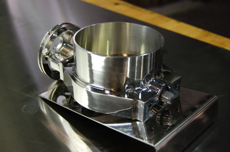
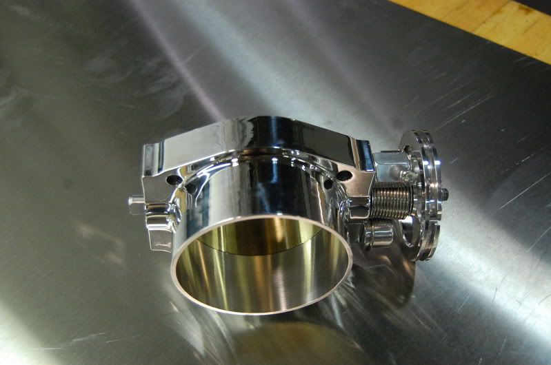
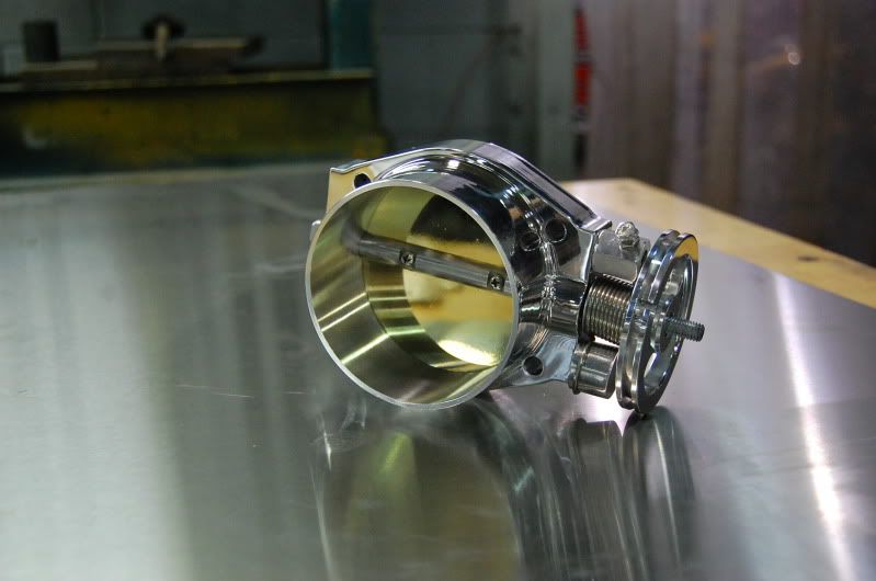
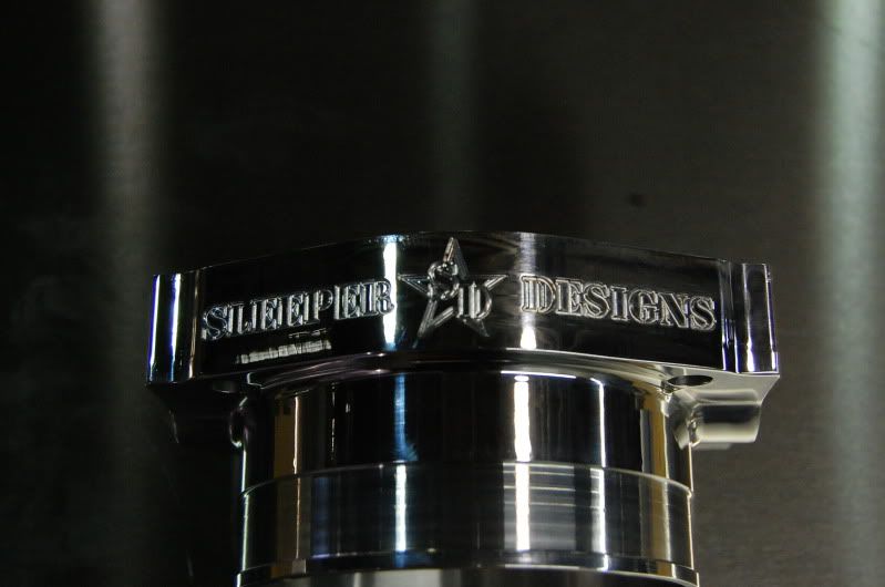
Sorry to have teased but I have more projects then you can imagine going on right now. This one is definitely on the back burner till I get a few new parts done and products released like this little sucker:
p1690557_1.jpg

p1690557_2.jpg

p1690557_3.jpg

p1690557_4.jpg

p1690557_5.jpg


Thanks,
Seth