swapping mkiv injectors in 1jz wireup help

chuckmuska2005

New Member
Dec 3, 2007
265
0
0
38
canton
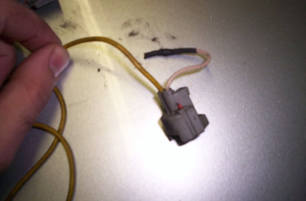
I got this resistor pack and it has it's own harness with the injector clips that fit on to the mkiv injectors. Issue is that there is one wire out of each injector clip that is cut and don't know how to wire it up. Here's a picture of one of the injector clips, they all look like this.

p1160737_1.jpg
 

chuckmuska2005

New Member
Dec 3, 2007
265
0
0
38
canton
I figure that the cut wire goes into the 1jz harness but don't know which wire on the factory 1jz harness. The black wire?, because the resistor pack already has power?? Or the black/orange, which I assume is the power wire to the injector clip.


Anyone, any ideas????????
 

dinhnerz

New Member
Mar 29, 2008
52
0
0
Cali
If you look at the wires on the injectors and clips, there should be 1 wire that is all the same color. That wire would be power. The other wire is ground that is supply by the PCM. Since there is only 4 wires coming out of the resister pack. 1 should be getting power to the resister pack while the other 3 should be power coming out of the pack. What you would want to do is either solder all of the same color wires on the injectors [harness side] to 1 different colored wire on the resister pack. Either that or solder 1 of the wire to the pack and cover up the rest. This supply power to the resister pack. The other 3 wires would power the injectors, What you would need to do is group 2 injectors together. Say 1&2, 3&4, 5&6. Each group would get a power source from one of the wire coming out of the resister pack.

Someone correct me if I'm wrong.

But if what you're saying is, you have power to the pack going into the clips. One wire on each clip is cut. That cut wire would be the ground wire going to the PCM.
 

chuckmuska2005

New Member
Dec 3, 2007
265
0
0
38
canton
dinhnerz;1161275 said:
If you look at the wires on the injectors and clips, there should be 1 wire that is all the same color. That wire would be power. The other wire is ground that is supply by the PCM. Since there is only 4 wires coming out of the resister pack. 1 should be getting power to the resister pack while the other 3 should be power coming out of the pack. What you would want to do is either solder all of the same color wires on the injectors [harness side] to 1 different colored wire on the resister pack. Either that or solder 1 of the wire to the pack and cover up the rest. This supply power to the resister pack. The other 3 wires would power the injectors, What you would need to do is group 2 injectors together. Say 1&2, 3&4, 5&6. Each group would get a power source from one of the wire coming out of the resister pack.

Someone correct me if I'm wrong.

But if what you're saying is, you have power to the pack going into the clips. One wire on each clip is cut. That cut wire would be the ground wire going to the PCM.

There are two wires on this resistor pack harness, yellow, like the rest of the harness, and white with a red stripe, the one that's cut. On the 1jz harness, there's black and black/orange. I'm guessing that black/orange is power seeing that black/orange is a power wire to the ignitor.

One idea is that the cut wire, white/red is the ground and the yellow is the power since the yellow is innertwined into this aftermarket harness and needs to be powered up. So maybe the white/red just needs to be hooked up to the black on the 1jz injector harness, hide the rest like you said and power up the resistor pack.

What I should do first is power up the resistor pack and test the yellow and white/red wires to see which receives power.
 

dinhnerz

New Member
Mar 29, 2008
52
0
0
Cali
You're correct. Black/orange is to power up the injectors. So you would take 1 of the black/orange wire and connect it to the resister pack [harness side] then from the resister pack connect to the injector clips. With the other wires on the injectors [ground side] just solder them on the harness side and get rid of the old clips.
 

chuckmuska2005

New Member
Dec 3, 2007
265
0
0
38
canton
So just use the black wire in the 1jz injector clip harness for the ground and power up the aftermarket resistor pack with a local power line, correct?
 

dinhnerz

New Member
Mar 29, 2008
52
0
0
Cali
Basicly here look at it this way.
Power = P [B+ power] G = Ground to PCM

injectors coming out of rail
Injectors 1 - 2 - 3 - 4 - 5 - 6
/| /| /| /| /| /|
p g p g p g p g p g p g
| | | | | | | | | | | |
fr fr fr fr fr fr

Resister pack side - FR = from resister pack
power into resister
B+ --- [pack]
| | | | | |
fr fr fr fr fr fr


Harnes side injectors
1 - 2 - 3 - 4 - 5 - 6
/| /| /| /| /| /|
p g p g p g p g p g p g
| | | | | |

choose one of the power wire on the harness side and connect it the B+ wire on the injectors.

If you're replacing the clips on the injectors, solder the new ground wire clip to the harness side on the original ground wire for each injector. Power should be coming out of the resister pack to power up the injectors. The ground side is the control side by the ECU [PCM].
 

dinhnerz

New Member
Mar 29, 2008
52
0
0
Cali
Didn't come out as good as it was suppose to. It deleted all the spaces in between. Anyways If you still don't understand I'll try to draw something out tomorrow for you.
 

dinhnerz

New Member
Mar 29, 2008
52
0
0
Cali
The black/orange wire on the harness side is to power up the resister, basically use that blk/oj wire to power up the injectors. There should be a blk/oj wire on each injector. The other one should be ground.
 

chuckmuska2005

New Member
Dec 3, 2007
265
0
0
38
canton
Actually, wondering what would be a good wire to tap into for power. Could I use the black/orange going into the ignitor??? I'm talking about the two wires that go into the ignitor not the big black clip with the signal wires. Would that work??????
 

pnutcar

1jz Asshole :)
Jan 25, 2006
299
0
0
St. Louis, MO
chuckmuska2005;1163784 said:
Actually, wondering what would be a good wire to tap into for power. Could I use the black/orange going into the ignitor??? I'm talking about the two wires that go into the ignitor not the big black clip with the signal wires. Would that work??????

Any switched 12+ will work.