
Alright so after trying to make sense of the infamous http://supraforums.com/forum/showthread.php?t=170792&highlight=resistor+wiring
thread, I went ahead and gave it a try. Well, after i got everything wired up the portion of the setup where the black injector wires from the ecu are wired to the white wire on the resistor (note, this is hardwired without the 7m resistor pigtail) seemed off. Prior to cutting and soldering there were 6 black wires that evetually formed 5 black wires near where the MAP sensor plugs in. The fifth wire was spliced together with grounds from 2 other sensors. See photo for better understanding. Everything appears fine except that 5th wire?!? Anyone have some insight?
This is the wiring diagram i used:
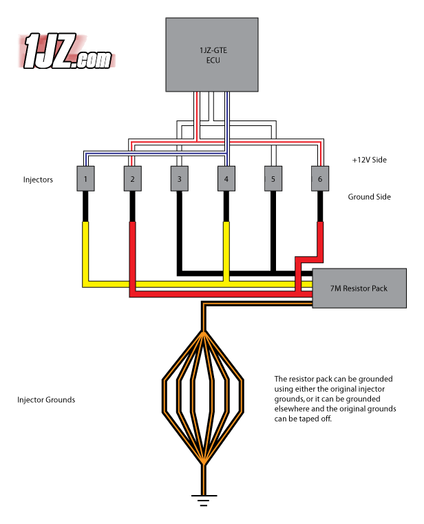
And this is the finished product: Note there are only 5 injector grounds rather than 6???I cant remember for the life of me where 2 of the grounds became one wire.

thread, I went ahead and gave it a try. Well, after i got everything wired up the portion of the setup where the black injector wires from the ecu are wired to the white wire on the resistor (note, this is hardwired without the 7m resistor pigtail) seemed off. Prior to cutting and soldering there were 6 black wires that evetually formed 5 black wires near where the MAP sensor plugs in. The fifth wire was spliced together with grounds from 2 other sensors. See photo for better understanding. Everything appears fine except that 5th wire?!? Anyone have some insight?
This is the wiring diagram i used:
And this is the finished product: Note there are only 5 injector grounds rather than 6???I cant remember for the life of me where 2 of the grounds became one wire.
