So this is how I'm going to post up the supplemental install guide for my remotestarter kits. This guide can be used for any of the units I sell or as a guide for one you may want to do yourself. If you are doing an alarm of keyless only you can still use the portions that apply here. I just going to go through the whole Alarm/Remote start/keyless to cover everything at one shot.
I will be updating this often as I get better pics or more complete details of other model years. My supra is an 89 turbo so most of the pics will be of this model year.I also have an 88 turbo parts car. I do know that some of the wiring is different between these two cars and can only assume it has to do with the changes in body styles and options. I would think that 86.5 to 88 would be simular as would be 89-92. Athough 90+ cars will have some additional changes due to airbags being added.
That being said please remember this is only a guide and you should still test your wiring with a computer safe test light or multi meter.
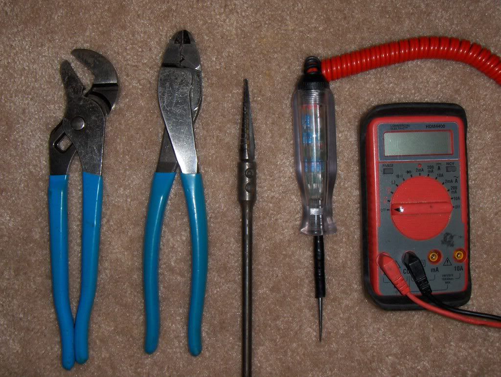
Ok before we start lets go over some of the tools that will be needed to do the job.
1. Phillips screwdriver
2. 10 mm socket and rachet of wrench.
3. Wire cutter/ crimpers (Channellock brand highly recomended)
4. Channel lock pliers (see photo for type I'm talking about, also Channellock brand)
5. razor knife.
6. Computer safe test light of multimeter. (DO NOT use a 12volt bulb type test light. It is easy to damage your car with one of these. If you are testing for neg. circuits and short your bcm you will want to punch yourself in the mouth for not listening to me.)
7.Cordless drill/screwdriver.
8. drill bit set or Unibit.
9. Electrical tape.
10. Some basic knowlegde of how to work on a car.
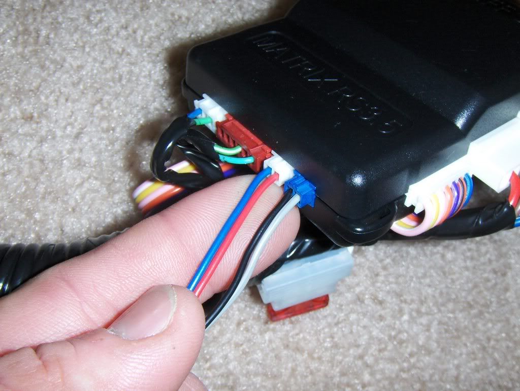
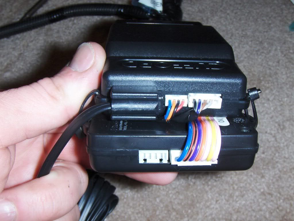
Ok now lets get to work. First lets take a look at what come out of the box you get from me.
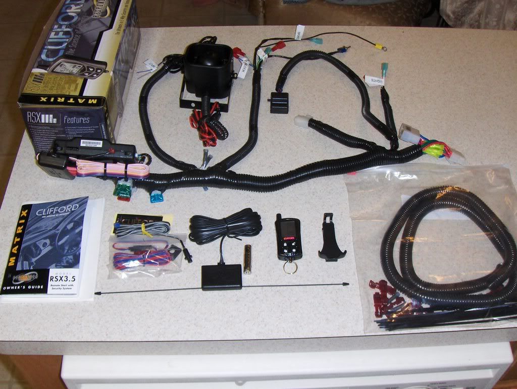
Familiarize yourself with the different components of the kit. Notice the labels on the ends of the wires. these will give you an idea of how these will be laid out in the car. Also take not of the seperate parts like the siren and LED and program switches. Also read through the install manual that come with the unit it is full of info on how to find the circuits in a car and also general info about module location and other concerns.
For right now I'm not including photos of how to disasemble your car because this would start to take up alot of space on here. But if I get a lot of requests for this i may do it later.
You will need to remove the drivers side lower dash. It has four screws holding it in place and two more holding the hood release handle to it. you will want to remove the air duct that runs behind this panel to ease access to space above the steering column. You will need to remove the drivers dead pedal. There are two bolts holding it down under the two caps.You will need to remove the drivers side door sill and kick panel. The sill is held in place by four screws and the kick panel is held in place by a plastic nut.
It will also be a good idea to remove the drivers side A-pillar cover, visor and header panel for easier routing of the ant. wires. You may also have to drop the domelight/mirror housing to drop the header panel.
Ok, now that your cars apart, some people like to disconnect their batteries at this point. I find this makes for a difficult process of finding wires so I don't recomend it but to each his own.
We'll start by mounting the ant. on the winshield. If your ant. only has one pole it should be mounted vertically, pointing down for the top edge of the windshield. If it has two poles it should be mounted horizontally, side to side. Run the wire behind the header and down the A pillar to the kick panel. Secure this to the A pillar with tape or to the existing wiring with wire ties. Reassemlbing the header panel and A pillar at this time is a good idea to clear up some of the parts laying around.
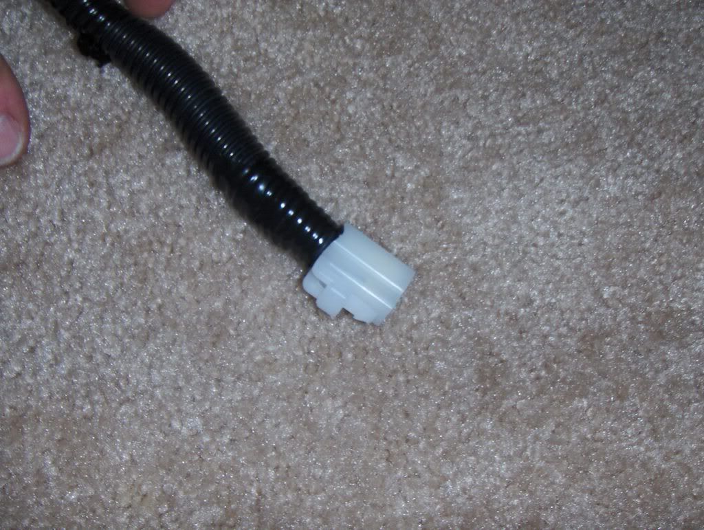
Next lets take a look at the part of the harness that goes down into the kick panel.
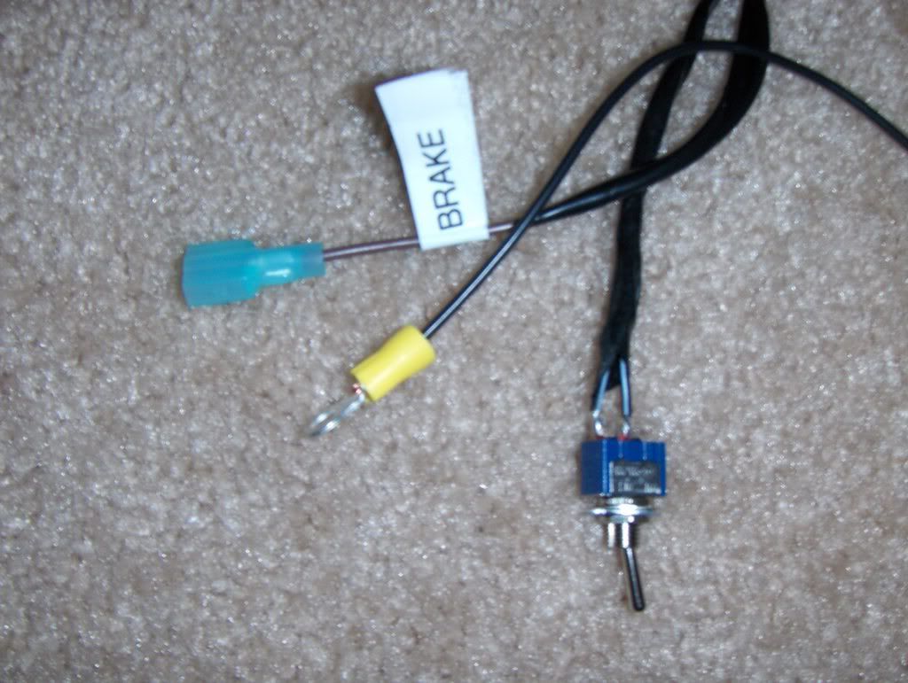
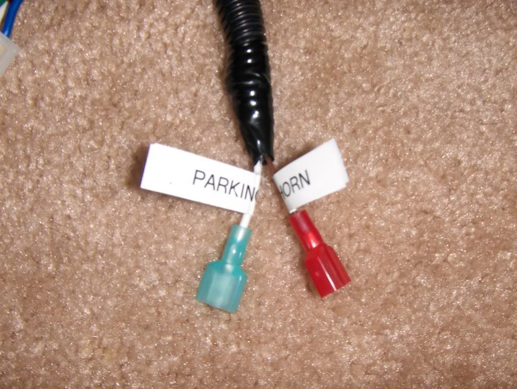
This is the very end of the kick panel harness. It has the brake wire, Remotestart control switch and ground eyelet.
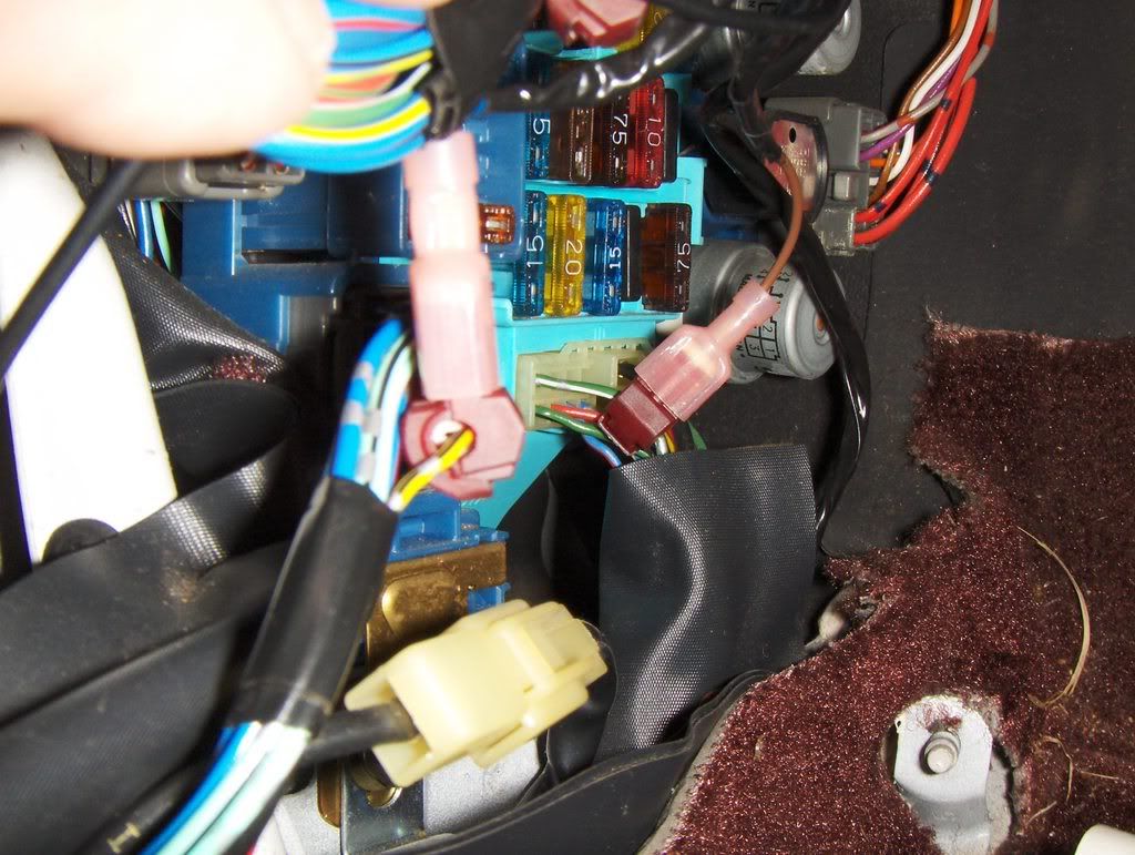
Just below the fuse box there is a bolt that can be used as a ground point. Attach the ground eyelet there.
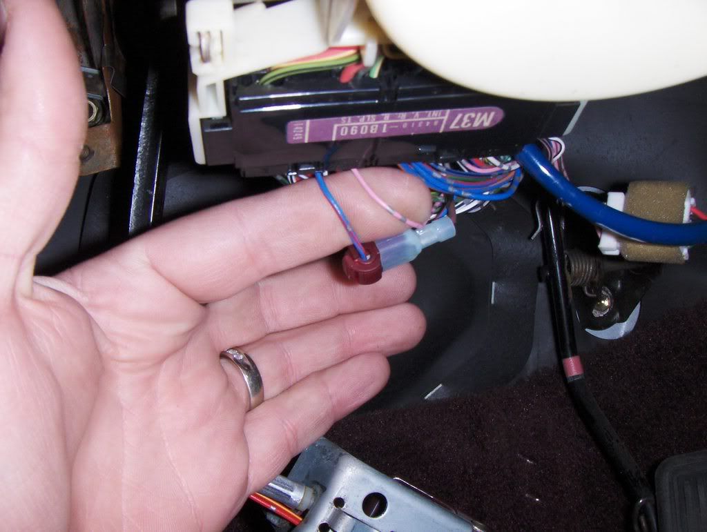
In the pic below you can see the green/white brake wire. t-tap that wire and attach the brown wire labeled brake wire to it.
In this pic you can also make out the yellow/black hood and trunk trigger wire. You will attach the blue wire labeled trunk there.
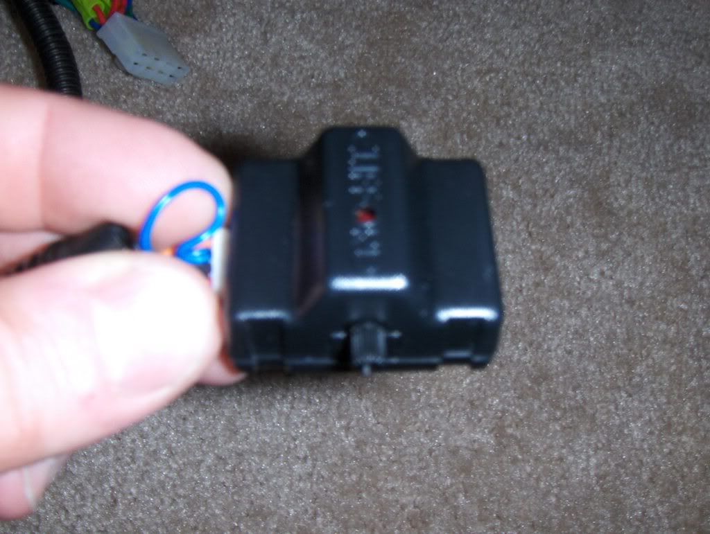
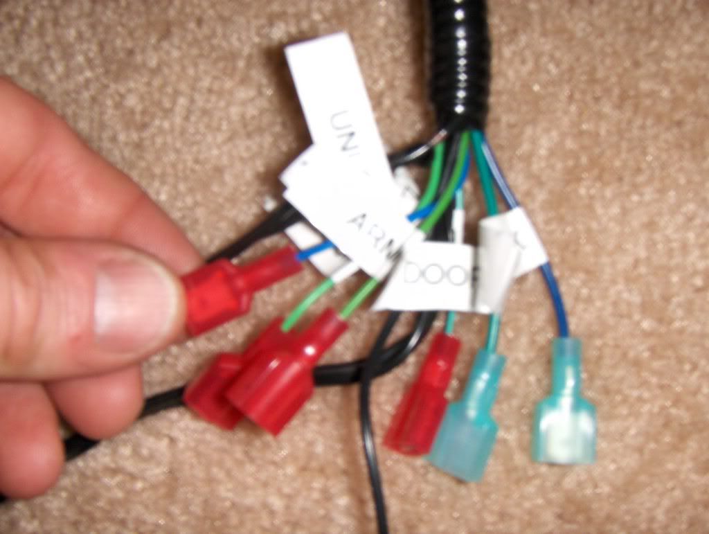
This pic is of the main portion of the kick panel harness.
This is a pic of the overall kickpanel area.
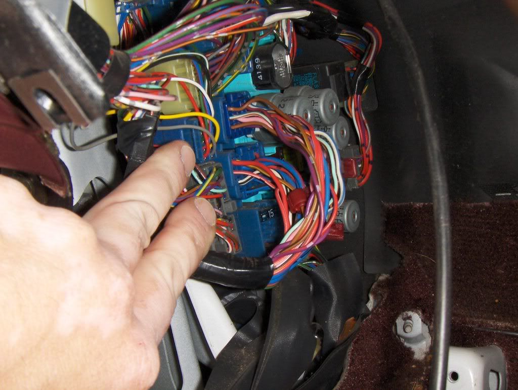
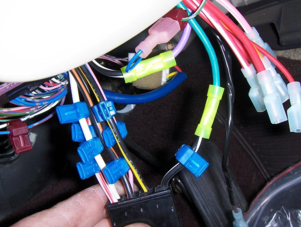
Notice the two blue plugs at the center of this pic. These are your door harness connectors. We are looking for a total of 5 wires here. Test for the lock and unlock wires using the door trim switch. Test for the Arm and Disarm wires using the key cylinder switch (turning a key in the driver's door key cylinder. The door trigger switch wire is also in the larger of these two connectors. All of these are negative swicthed wires. Meaning when the switch makes contact you will see ground on the apprpriate wire.
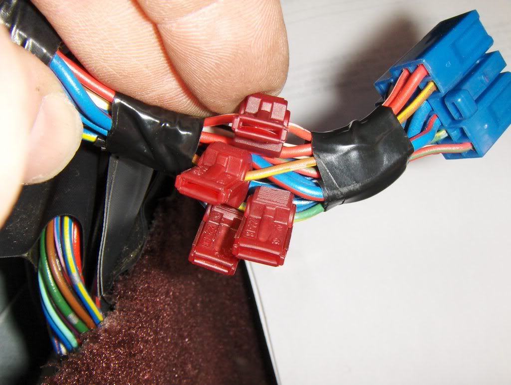
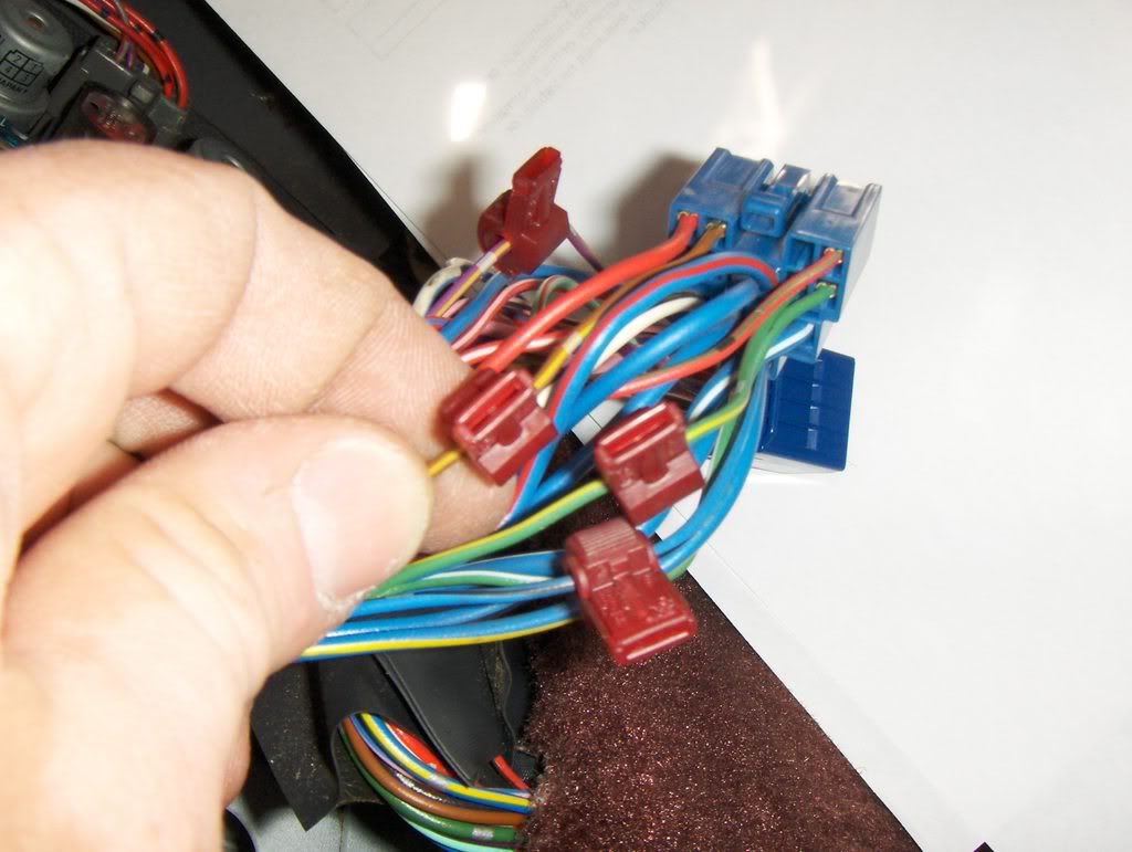
This is a pic of the larger blue conn. At the top is the red/white Door Trigger wire. Just below that is the brown/yellow Arm wire, green/yellow Lock wire. and at the bottom but not really visable is the blue/black Unlock wire.
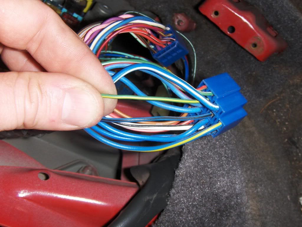
Here is a better pic of the green/yellow Lock wire and the blue/black Unlock wire.
In this pic you can see the violet/yellow Disarm wire. It is in the smaller blue conn.
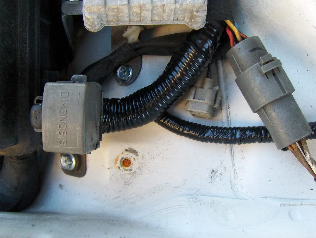
Ok now let's got out under the hood and find our tach wire. Just behind the driver's side shock tower is the diagnostics plug.
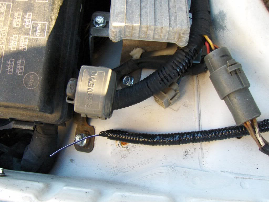
Here you can see that I've run my tach lead out to the Diag. con. It is the violet/white wire in the loom labeled Tach.
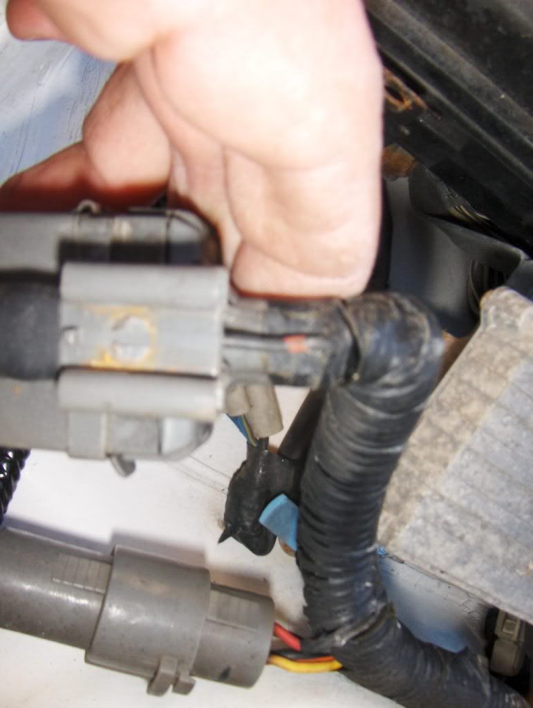
In this pic you can see the tach wire we are looking for is actually in its own connector on the back of the diag. conn. It is the black w/ red bands wire running on the outside of the harness. Most of the tape and loom around here will be very brittle and probably just crumble away once you start to handle it. As you can see in the next couple of pics i decided to just cut it away and replace it.
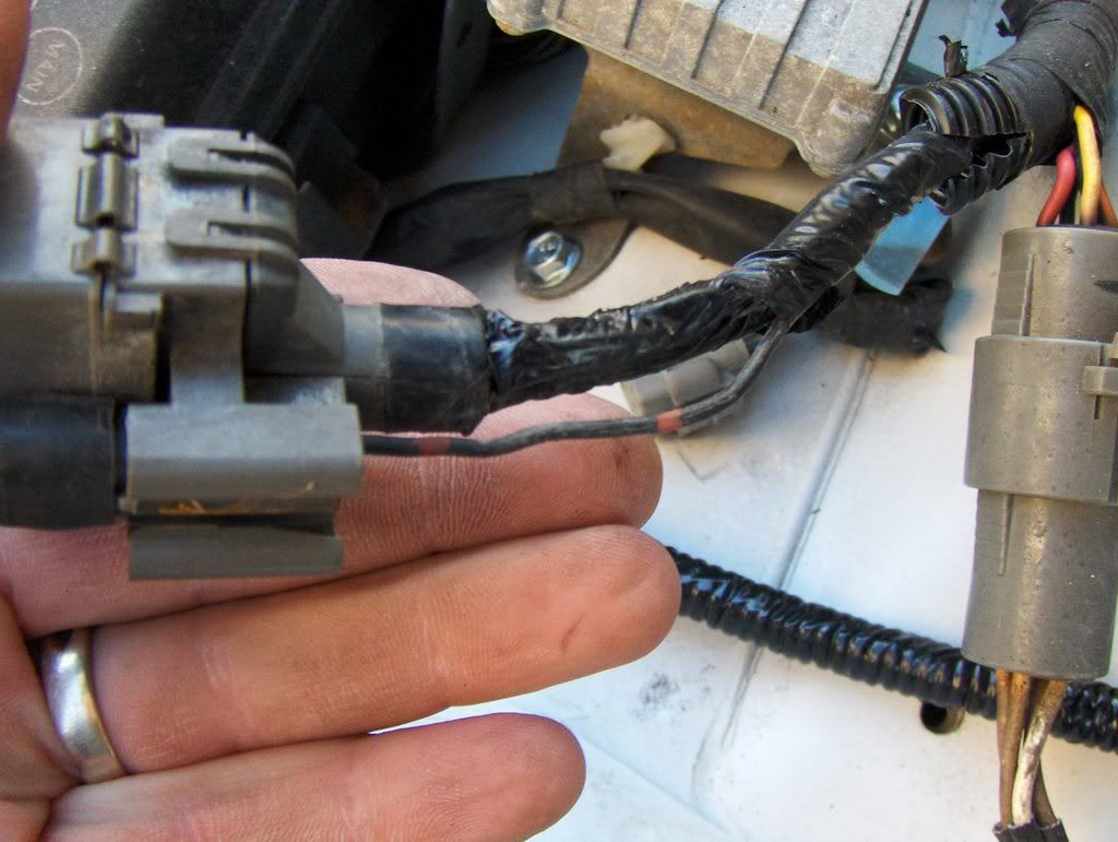
In my opinion the best type of connection to make here is a splice using a crimped butt connector. Do not use a t-tap out under the hood.
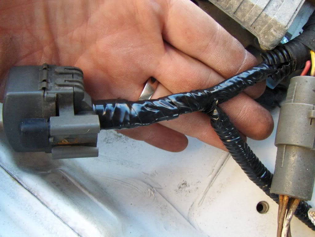
Make sure to tape up this splice very well to protect from corrosion. And finally wrap it up in loom.
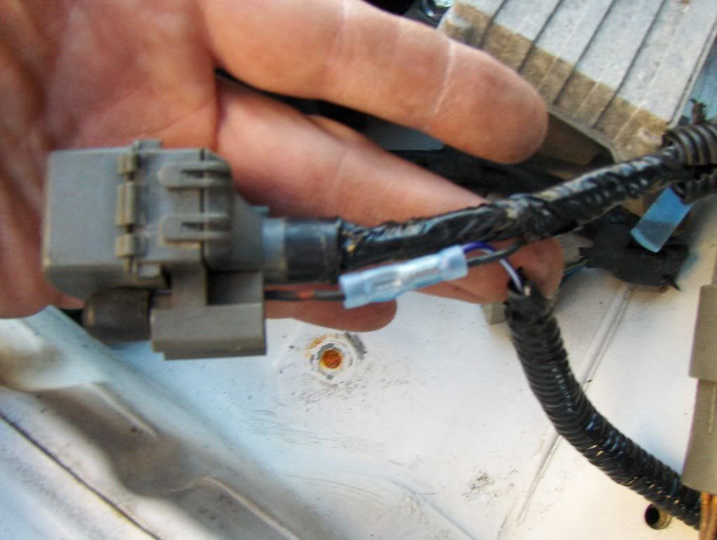
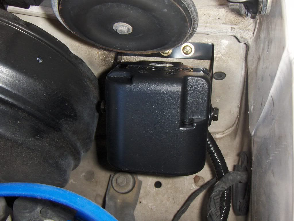
While we're out here we can also mount the siren and run its wiring back into the car.Here is a pic of where I mounted my siren. Just below the siren is a factory grommet through which I ran my wires.
If you want to install a remote start cutoff hood switch now is the time to do it . I personally dont recomend it, just because both pin type and mercury type swithes are prone to failure. If you are worried about protecting you car from having its hood opened, the alarm will already be connected to the factory hood switch wire which is the same wire as the trunk trigger in the kick. For those of you who want to connect the the hood cutoff wire it is the grey wire labeled hood loomed together with the tach wire.
Back inside the car we will look at where the srien wire will be connected.
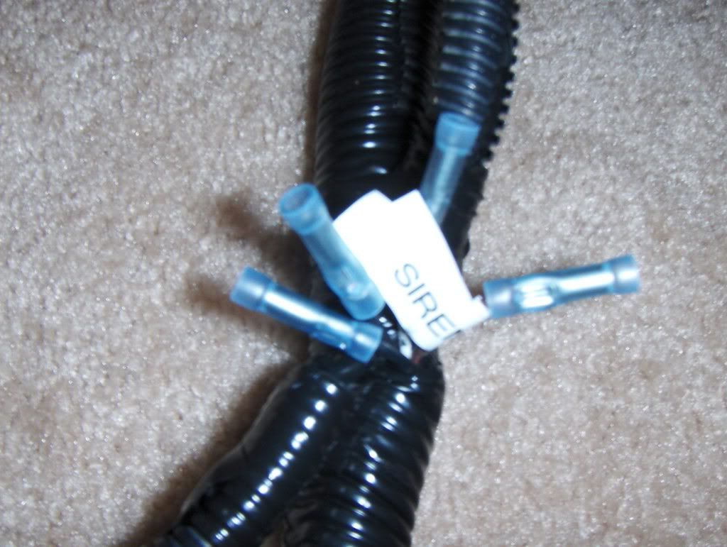
Here you can see the pigtails I've left for the siren. Just connect the red siren wire to the brown wire labeled siren and connect the black wire to one of the two black pigtails.
In this pic you can also see the white/blue negative start input wire. this input can be used to initiate the remote starter by using a push button switch or other device. I have a hidden switch in my car so i can activate the remote start without using the remote.
OK, by now just about everything in the kick panel should be connected. So lets take a look at the Ignition switch t-harness.
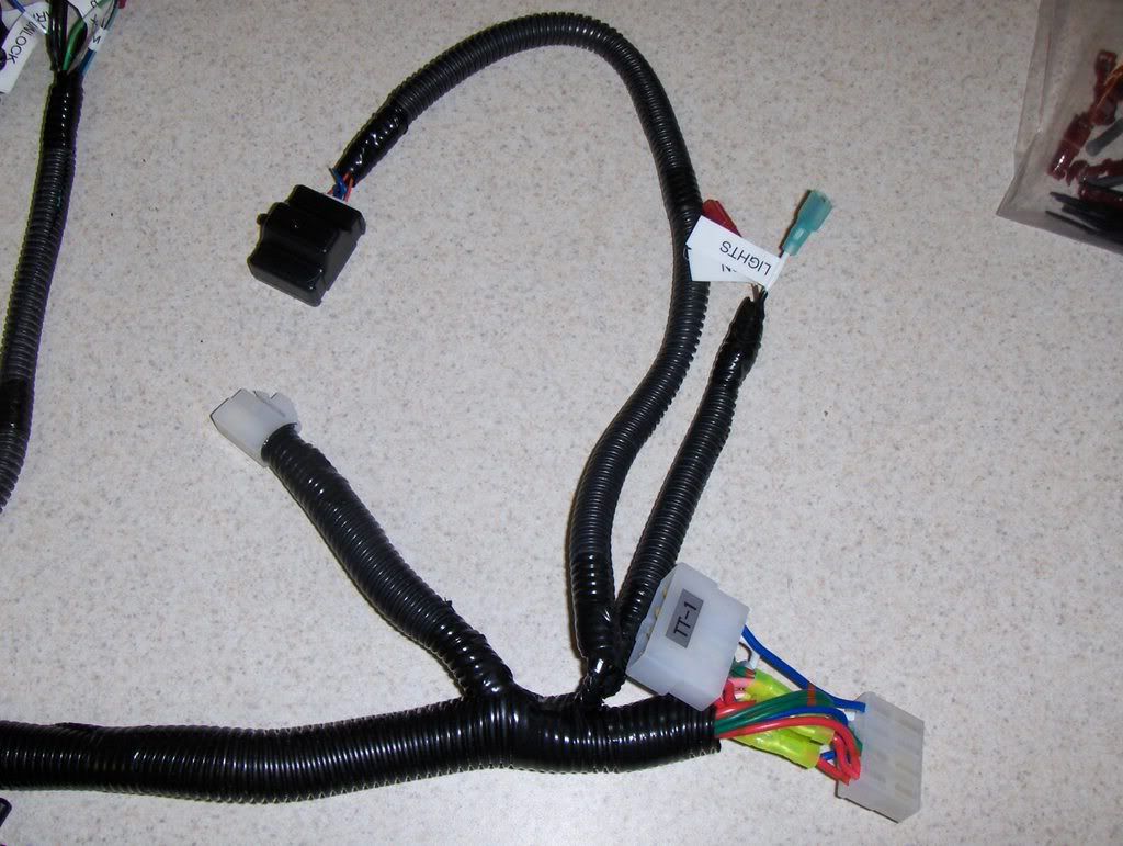
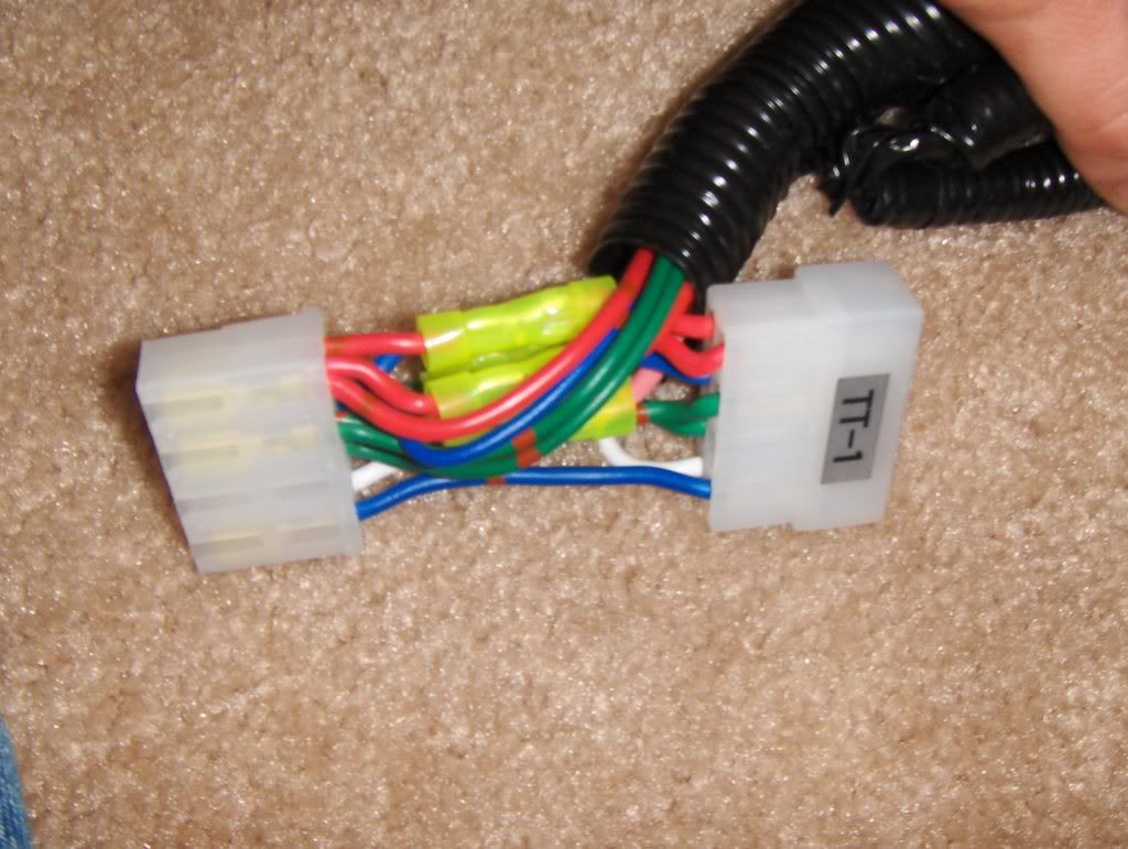
Here you can see the two plugs that make up the ignition connector T.
You should route this OVER the steering column. Take care to secure it so that it does not come into contact with the steering shaft. Make sure you test this with the full range of motion of both the tilt and telescope adjustments. If the harness get caught by the steering shaft you will want to set yourself on fire for letting that happen, so double check your work.
This is a pic of the ignition switch connector. It is this black conn. on the right with the rubber boot.
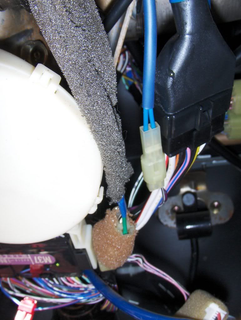
Now unplug your ign. conn. and plug in the t-harness. Plug the ign. conn. back into the t-harness.
Continued Below at post # 9
I will be updating this often as I get better pics or more complete details of other model years. My supra is an 89 turbo so most of the pics will be of this model year.I also have an 88 turbo parts car. I do know that some of the wiring is different between these two cars and can only assume it has to do with the changes in body styles and options. I would think that 86.5 to 88 would be simular as would be 89-92. Athough 90+ cars will have some additional changes due to airbags being added.
That being said please remember this is only a guide and you should still test your wiring with a computer safe test light or multi meter.
Ok before we start lets go over some of the tools that will be needed to do the job.
1. Phillips screwdriver
2. 10 mm socket and rachet of wrench.
3. Wire cutter/ crimpers (Channellock brand highly recomended)
4. Channel lock pliers (see photo for type I'm talking about, also Channellock brand)
5. razor knife.
6. Computer safe test light of multimeter. (DO NOT use a 12volt bulb type test light. It is easy to damage your car with one of these. If you are testing for neg. circuits and short your bcm you will want to punch yourself in the mouth for not listening to me.)
7.Cordless drill/screwdriver.
8. drill bit set or Unibit.
9. Electrical tape.
10. Some basic knowlegde of how to work on a car.
Ok now lets get to work. First lets take a look at what come out of the box you get from me.
Familiarize yourself with the different components of the kit. Notice the labels on the ends of the wires. these will give you an idea of how these will be laid out in the car. Also take not of the seperate parts like the siren and LED and program switches. Also read through the install manual that come with the unit it is full of info on how to find the circuits in a car and also general info about module location and other concerns.
For right now I'm not including photos of how to disasemble your car because this would start to take up alot of space on here. But if I get a lot of requests for this i may do it later.
You will need to remove the drivers side lower dash. It has four screws holding it in place and two more holding the hood release handle to it. you will want to remove the air duct that runs behind this panel to ease access to space above the steering column. You will need to remove the drivers dead pedal. There are two bolts holding it down under the two caps.You will need to remove the drivers side door sill and kick panel. The sill is held in place by four screws and the kick panel is held in place by a plastic nut.
It will also be a good idea to remove the drivers side A-pillar cover, visor and header panel for easier routing of the ant. wires. You may also have to drop the domelight/mirror housing to drop the header panel.
Ok, now that your cars apart, some people like to disconnect their batteries at this point. I find this makes for a difficult process of finding wires so I don't recomend it but to each his own.
We'll start by mounting the ant. on the winshield. If your ant. only has one pole it should be mounted vertically, pointing down for the top edge of the windshield. If it has two poles it should be mounted horizontally, side to side. Run the wire behind the header and down the A pillar to the kick panel. Secure this to the A pillar with tape or to the existing wiring with wire ties. Reassemlbing the header panel and A pillar at this time is a good idea to clear up some of the parts laying around.
Next lets take a look at the part of the harness that goes down into the kick panel.
This is the very end of the kick panel harness. It has the brake wire, Remotestart control switch and ground eyelet.
Just below the fuse box there is a bolt that can be used as a ground point. Attach the ground eyelet there.
In the pic below you can see the green/white brake wire. t-tap that wire and attach the brown wire labeled brake wire to it.
In this pic you can also make out the yellow/black hood and trunk trigger wire. You will attach the blue wire labeled trunk there.
This pic is of the main portion of the kick panel harness.
This is a pic of the overall kickpanel area.
Notice the two blue plugs at the center of this pic. These are your door harness connectors. We are looking for a total of 5 wires here. Test for the lock and unlock wires using the door trim switch. Test for the Arm and Disarm wires using the key cylinder switch (turning a key in the driver's door key cylinder. The door trigger switch wire is also in the larger of these two connectors. All of these are negative swicthed wires. Meaning when the switch makes contact you will see ground on the apprpriate wire.
This is a pic of the larger blue conn. At the top is the red/white Door Trigger wire. Just below that is the brown/yellow Arm wire, green/yellow Lock wire. and at the bottom but not really visable is the blue/black Unlock wire.
Here is a better pic of the green/yellow Lock wire and the blue/black Unlock wire.
In this pic you can see the violet/yellow Disarm wire. It is in the smaller blue conn.
Ok now let's got out under the hood and find our tach wire. Just behind the driver's side shock tower is the diagnostics plug.
Here you can see that I've run my tach lead out to the Diag. con. It is the violet/white wire in the loom labeled Tach.
In this pic you can see the tach wire we are looking for is actually in its own connector on the back of the diag. conn. It is the black w/ red bands wire running on the outside of the harness. Most of the tape and loom around here will be very brittle and probably just crumble away once you start to handle it. As you can see in the next couple of pics i decided to just cut it away and replace it.
In my opinion the best type of connection to make here is a splice using a crimped butt connector. Do not use a t-tap out under the hood.
Make sure to tape up this splice very well to protect from corrosion. And finally wrap it up in loom.
While we're out here we can also mount the siren and run its wiring back into the car.Here is a pic of where I mounted my siren. Just below the siren is a factory grommet through which I ran my wires.
If you want to install a remote start cutoff hood switch now is the time to do it . I personally dont recomend it, just because both pin type and mercury type swithes are prone to failure. If you are worried about protecting you car from having its hood opened, the alarm will already be connected to the factory hood switch wire which is the same wire as the trunk trigger in the kick. For those of you who want to connect the the hood cutoff wire it is the grey wire labeled hood loomed together with the tach wire.
Back inside the car we will look at where the srien wire will be connected.
Here you can see the pigtails I've left for the siren. Just connect the red siren wire to the brown wire labeled siren and connect the black wire to one of the two black pigtails.
In this pic you can also see the white/blue negative start input wire. this input can be used to initiate the remote starter by using a push button switch or other device. I have a hidden switch in my car so i can activate the remote start without using the remote.
OK, by now just about everything in the kick panel should be connected. So lets take a look at the Ignition switch t-harness.
Here you can see the two plugs that make up the ignition connector T.
You should route this OVER the steering column. Take care to secure it so that it does not come into contact with the steering shaft. Make sure you test this with the full range of motion of both the tilt and telescope adjustments. If the harness get caught by the steering shaft you will want to set yourself on fire for letting that happen, so double check your work.
This is a pic of the ignition switch connector. It is this black conn. on the right with the rubber boot.
Now unplug your ign. conn. and plug in the t-harness. Plug the ign. conn. back into the t-harness.
Continued Below at post # 9
Last edited: