So I've spent the last few hours trying to figure out what are possible ways to get this to work. What got me going on this is this post from LilMissmkII about how her tuner got it to work http://www.supramania.com/forums/showthread.php?79287-mapecu2-timing-control/page2
The first part of this is understanding how the 7-mgte ignition works.
Here's a link to where I got the info about toyota ign system http://www.toymods.net/forums/showthread.php?t=10003
First off, we need to know who the main players are, take a look at this wiring diagram below and look for
-IGT
-IGF
-IGDA
-IGDB
-G1
-G2
-NE

now read this passage that I took from the above link (here the author is talking about a dissy ign, which is irrelevant to the 7mgte but the information is relevant)
"In short, what happens is the dissy is obviously spinning with engine RPM, and generating the variable reluctance (VR) signals "G1" and "Ne". Ne is the cam position signal from the multi-tooth wheel, giving the ECU the exact rotational position of the engine within it's cycle. G1 is a reference signal that the ECU can use to determine what cylinder the engine is up to.
The ECU reads these signals, then applies it's ignition advance according to its programmed ignition map, and sends the IGt signal out to the Igniter.
The igniter fires the ignition coil according to the IGt signal.
The igniter also generates a return signal to the ECU - IGf - to let the ECU know that the ignition event was sucessful."
Now remember that
-IGt takes the information from the ecu and sends it to the igniter.
Now take a look at this passage from that same link from above
"The main difference between the DLI system and the single coil system is the igniter. These are a special kind of igniter that have extra inputs to determine which coil is fired. Notice in the system above the extra "G" signal and the "IGda" and "IGdb" signals - these are how the system knows which coil pack to fire. The two G sensors - G1 and G2 provide the "reference" signals to the ECU which the ECU uses to pick which coil pack to fire.
The ECU then ouputs the IGt signal as normal, but also outputs an IGDa and IGDb signal to the igniter so that the igniter can fire the correct coil pack."
Now remember that
-IGda and IGdb determine which coil to fire and that's it! and that IGt signals as normal
Now lets bring everything back to map ecu's timing diagram
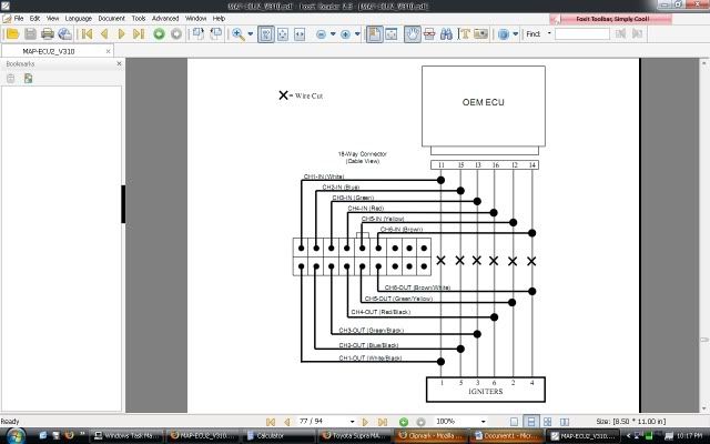
here's Map ecu's I6 coil and plug diagram

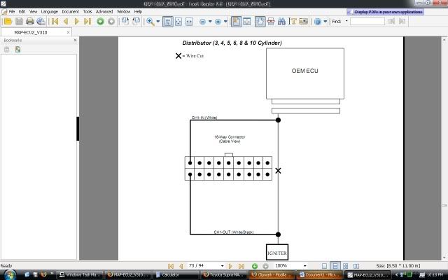
here's map ecu's dizzy diagram

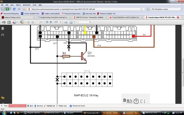
and here's map ecu's diagram for 7mge wiring

-Now we know that the I6 coil and plug diagram doesn't work because we don't have 6 ecu outputs going to the igniters
-What we have going to the igniters are IGda, IGdb, and IGt
-We know that map ecu cannot control IGda or IGdb because there's no correct way for map ecu to know the signals the ecu is giving these guys, but the thing is we don't need to worry about that. All we need to worry about is making sure that we pick up IGt signals via map ecu. We do this by wiring it as if we had a dizzy on our car. Map ecu will pick up the ecu signal and send it to IGt. IGt will send the signal out to the igniter. IGda and IGdb will know which coil to send it to and IGf will send its signal to the ecu letting it know that the information was received.
So what's going on is the ecu will know our boost and rpm it will then send the necessary info to IGt on what timing should be at, but map ecu will intercept this information and adjust timing by your settings at those rpm and boost point. IGda and IGdb will know which coil needs to send spark to which cylinder and will send only that signal, while IGt sends the information as to what degree spark will occur.
That's all I have for now, let me know what you guys thinks?
The first part of this is understanding how the 7-mgte ignition works.
Here's a link to where I got the info about toyota ign system http://www.toymods.net/forums/showthread.php?t=10003
First off, we need to know who the main players are, take a look at this wiring diagram below and look for
-IGT
-IGF
-IGDA
-IGDB
-G1
-G2
-NE

now read this passage that I took from the above link (here the author is talking about a dissy ign, which is irrelevant to the 7mgte but the information is relevant)
"In short, what happens is the dissy is obviously spinning with engine RPM, and generating the variable reluctance (VR) signals "G1" and "Ne". Ne is the cam position signal from the multi-tooth wheel, giving the ECU the exact rotational position of the engine within it's cycle. G1 is a reference signal that the ECU can use to determine what cylinder the engine is up to.
The ECU reads these signals, then applies it's ignition advance according to its programmed ignition map, and sends the IGt signal out to the Igniter.
The igniter fires the ignition coil according to the IGt signal.
The igniter also generates a return signal to the ECU - IGf - to let the ECU know that the ignition event was sucessful."
Now remember that
-IGt takes the information from the ecu and sends it to the igniter.
Now take a look at this passage from that same link from above
"The main difference between the DLI system and the single coil system is the igniter. These are a special kind of igniter that have extra inputs to determine which coil is fired. Notice in the system above the extra "G" signal and the "IGda" and "IGdb" signals - these are how the system knows which coil pack to fire. The two G sensors - G1 and G2 provide the "reference" signals to the ECU which the ECU uses to pick which coil pack to fire.
The ECU then ouputs the IGt signal as normal, but also outputs an IGDa and IGDb signal to the igniter so that the igniter can fire the correct coil pack."
Now remember that
-IGda and IGdb determine which coil to fire and that's it! and that IGt signals as normal
Now lets bring everything back to map ecu's timing diagram
here's Map ecu's I6 coil and plug diagram

here's map ecu's dizzy diagram

and here's map ecu's diagram for 7mge wiring

-Now we know that the I6 coil and plug diagram doesn't work because we don't have 6 ecu outputs going to the igniters
-What we have going to the igniters are IGda, IGdb, and IGt
-We know that map ecu cannot control IGda or IGdb because there's no correct way for map ecu to know the signals the ecu is giving these guys, but the thing is we don't need to worry about that. All we need to worry about is making sure that we pick up IGt signals via map ecu. We do this by wiring it as if we had a dizzy on our car. Map ecu will pick up the ecu signal and send it to IGt. IGt will send the signal out to the igniter. IGda and IGdb will know which coil to send it to and IGf will send its signal to the ecu letting it know that the information was received.
So what's going on is the ecu will know our boost and rpm it will then send the necessary info to IGt on what timing should be at, but map ecu will intercept this information and adjust timing by your settings at those rpm and boost point. IGda and IGdb will know which coil needs to send spark to which cylinder and will send only that signal, while IGt sends the information as to what degree spark will occur.
That's all I have for now, let me know what you guys thinks?
Last edited:
