alrighty saves people scratching there heads when they finally want to install one of theres babies due to japanese instructions and shit english on there website, in all honestly the installation is quite basic a 10yr old could do it blind folded 
anyhow
bee*R website state the below to install it onto a toyota.... (talk about being generalised) so using the below install diagram

they are asking you to splice in to IGF & NE for your signals then your basics for making the unit operate.
BEE*R limiter wire colours and what they do:
RED
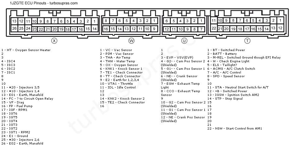
Please refer to the pinout diagram below, and connect it to the designated vehicle's ECU B+.
BLACK
Connect this wire to theh vehicle's chassis' earth/ground contact, or the the vehicle's battery earth/ground terminal.
YELLOW
This wire is for the RPM signal. this is IGF on the below jza70 ecu pinout
GREEN
This wire is for the ignition signal. but for us jza70 users thats NE on the below pinout.
WHITE
This wire is for the side brake switch signal. jsut needs a ground input (re via a switch, hanbrake [or use it as for flat shifting via clutch]) this doesnt have to be used if you don't want too this is used for dial "REV 2" for launch control.

using the above pinout:
1.) connect/splice yellow (NE) wire from rev limiter to X17 (X being plug type, 17 being pin on diagram above) *NOTE PLEASE SHIELD YOUR CONNECTION*
2.) connect/splice green (IGF) wire from rev limiter to U12 (U being plug type, 12 being pin on diagram above)*NOTE PLEASE SHIELD YOUR CONNECTION*
3.) connect/splice red (+12v) wire from rev limiter to T12 (T being plug type, 12 being pin on diagram above)
4.) connect black wire from rev limiter to ground or X24 (X being plug type, 24 being pin on diagram above)
**NOTE** all connects need only to be joined do not disconnect signal to ecu or engine this is only an interuption device

BEE*R dial settings and features below:
REV-1:
To set up standard RPM (your new REV LIMIT).
0 2500
1 3000
2 3500
3 4000
4 4500
5 5000
6 5500
7 6000
8 6500
9 7000
A 7500
B 8000
C 8500
D 9000
E 9500
F 10000
REV-2:
The white wire / white dial for launch control. It works using an external switch or signal ( inputting a negative signal).
GAIN:
Controls the engine RPM cut off setting. For example, 0 is off, and 1 through to F is the adjustment range. The standard initial setting is 6. The lower the number the quicker the cut.
e.g. 1 = bababababa through to F = BANG!!!... BANG!!!... IF you set the GAIN to 0 the limiter wil not function.
[video=youtube;jP5dDWCs0f4]http://youtube.com/watch?v=jP5dDWCs0f4[/video]
in-cabin vid (phone spec)
[video=youtube;s6qD3AWT5I8]http://youtube.com/watch?v=s6qD3AWT5I8[/video]
night time outside car (ignore the "damn" knob!)
anyhow
bee*R website state the below to install it onto a toyota.... (talk about being generalised) so using the below install diagram

they are asking you to splice in to IGF & NE for your signals then your basics for making the unit operate.
BEE*R limiter wire colours and what they do:
RED
Please refer to the pinout diagram below, and connect it to the designated vehicle's ECU B+.
BLACK
Connect this wire to theh vehicle's chassis' earth/ground contact, or the the vehicle's battery earth/ground terminal.
YELLOW
This wire is for the RPM signal. this is IGF on the below jza70 ecu pinout
GREEN
This wire is for the ignition signal. but for us jza70 users thats NE on the below pinout.
WHITE
This wire is for the side brake switch signal. jsut needs a ground input (re via a switch, hanbrake [or use it as for flat shifting via clutch]) this doesnt have to be used if you don't want too this is used for dial "REV 2" for launch control.

using the above pinout:
1.) connect/splice yellow (NE) wire from rev limiter to X17 (X being plug type, 17 being pin on diagram above) *NOTE PLEASE SHIELD YOUR CONNECTION*
2.) connect/splice green (IGF) wire from rev limiter to U12 (U being plug type, 12 being pin on diagram above)*NOTE PLEASE SHIELD YOUR CONNECTION*
3.) connect/splice red (+12v) wire from rev limiter to T12 (T being plug type, 12 being pin on diagram above)
4.) connect black wire from rev limiter to ground or X24 (X being plug type, 24 being pin on diagram above)
**NOTE** all connects need only to be joined do not disconnect signal to ecu or engine this is only an interuption device

BEE*R dial settings and features below:
REV-1:
To set up standard RPM (your new REV LIMIT).
0 2500
1 3000
2 3500
3 4000
4 4500
5 5000
6 5500
7 6000
8 6500
9 7000
A 7500
B 8000
C 8500
D 9000
E 9500
F 10000
REV-2:
The white wire / white dial for launch control. It works using an external switch or signal ( inputting a negative signal).
GAIN:
Controls the engine RPM cut off setting. For example, 0 is off, and 1 through to F is the adjustment range. The standard initial setting is 6. The lower the number the quicker the cut.
e.g. 1 = bababababa through to F = BANG!!!... BANG!!!... IF you set the GAIN to 0 the limiter wil not function.
[video=youtube;jP5dDWCs0f4]http://youtube.com/watch?v=jP5dDWCs0f4[/video]
in-cabin vid (phone spec)
[video=youtube;s6qD3AWT5I8]http://youtube.com/watch?v=s6qD3AWT5I8[/video]
night time outside car (ignore the "damn" knob!)

