In case anyone is interested - might it be worth having a look at this:
http://cgi.ebay.co.uk/ws/eBayISAPI.dll?ViewItem&item=290361916783
?
http://cgi.ebay.co.uk/ws/eBayISAPI.dll?ViewItem&item=290361916783
?
3p141592654;1447833 said:Mode 2 is used when running with external ROM. From the factory they run mode 7 to use internal ROM.
You're interrupt table looks a little weird to me. Using your nomenclature, I would not expect IRQs 01-06 to point to the same address. What is this code from?
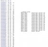
     D8X	HC11G5
01: ASR		PG7
02: ASR0	XIRQ
03: ~NMI
04: IRP		GND
05: IRL		MODA/LIR
06: Xin		MODA/LIR
07: Xout
08: CCLK
09: ADR
10: IS/~RD
11: OS/~WR
12: I/~E
13: CLK		VSSL
14: Sin3	PB1/A9
15: Sin2	PB2/A10
16: Sin1	PB3/A11
17: Sin0	PB4/A12
18: Sout1	PB5/A13
19: Sout0	PB6/A14
20: PB7/A7	PB7/A15
21: PB6/A6	PC7/D7
22: PB5/A5	PC6/D6
23: PB4/A4	PC5/D5
24: PB3/A3	PC4/D4
25: PB2/A2	PC3/D3
26: PB1/A1	PC2/D2
27: PB0/A0	PC1/D1
28: PA7/A15	PC0/D0
29: PA6/A14	R/W
30: PA5/A13	E
31: PA4/A12	Vrh
32: GND


") ). Let the disassemblers/coders do thier magic. The group is busy and they work on their own time lines.... do not get offended if your post was deleted, if I didn't see code or part information. It probably got the axe.
). Let the disassemblers/coders do thier magic. The group is busy and they work on their own time lines.... do not get offended if your post was deleted, if I didn't see code or part information. It probably got the axe.