1987 Supra Turbo Build * Running first factory LHD Digidash Swap*

Pyro15D

kind of a lucky dude
Aug 24, 2008
646
2
18
Whidbey Island, Washington
Hey everyone, my name is Dane and this is the build thread of my car. Now, to start off with, I’m 27 and am in the Navy, stationed in Whidbey Island, Washington. The car is a 1987 Black targa top Supra Turbo with a brown interior and a smell of mold. The car was free to me because it wouldn’t start. That ended up being a pretty simple matter of setting the cam timing correctly (the exhaust cam was off by 90 degrees). The car now runs and drives, but needs a lot of work. For one, that interior has to go. I have a spare car with a grey interior however, so the swap to a better interior begins! Anyway, goals for the car:
Megasquirt 2 with anti lag and launch control
57 trim ct26 (maybe 58) *Running Ball Bearing Boss Jr instead*
89+ tails-DONE
89+ wing-DONE
560cc injectors-DONE
Afpr-DONE
Walbro pump-DONE
Clear front turn signals-DONE
Install A/C from the other car and convert to r134-DONE
Tanabe Hyper Medallion exhaust *Running HKS Super Drager Exhaust and LOVE it!*
Fix the oil leak from the oil cooler lines-Done
Fix the power steering fluid leak-Replaced with a Reman rack and the rack STILL leaks. FML
Short shifter-Installed Marlin Crawler bushings
Innovate LC-1-DONE
EGT gauge
A-pillar gauge pod-DONE
Kenwood DNX5140-DONE
Polk DB501's-DONE
Grey interior-DONE
New carpet-DONE
And anything else I think of along the way…

Anyway, here are some pictures for you guys. This build thread should hopefully get pretty interesting. I will upload more pictures tonight of the interior work I have done so far.

phpHp8Na9PM.jpgphpRnQFLzPM.jpg
 
Last edited:

Pyro15D

kind of a lucky dude
Aug 24, 2008
646
2
18
Whidbey Island, Washington
Okay, here are some more pictures of the progress I have gotten done so far.

Pulling out the old interior...
phpKPxln9PM.jpg

And the old cracked dash...
phpxUCSi9PM.jpg

Bare floor ready to be vacuumed and cleaned up...
phpMT64ipPM.jpg

Borrowing the wife's side of the garage for a bit. This is a lot of stuff!
phpycF9DlPM.jpg

My wideband arrived in the mail. Sweet!
phpSron32PM.jpg

The wiring harness I am going to modify to run Megasquirt...
phpT1ysTsPM.jpg

New interior partly installed...
phpFRos9rPM.jpg

Now, I was wondering how you remove the grip for the handbrake? I have no idea.
 

Pyro15D

kind of a lucky dude
Aug 24, 2008
646
2
18
Whidbey Island, Washington
Thanks for the advice. I'll check that out. Anyway, I made a bit more progress with the megasquirt unit. I already had one built for the Delorean I used to own, so I just have to modify it for use with the 7m. I pretty much did exactly what speedfreak426 did to run the stepper motor idle air control valve. It was pretty easy, except I did find out that the stepper motor takes 125 steps from open to closed. It is recommended that for the start position, the ecu drives the motor a few steps past its maximum to ensure that it is completely open. There is no position sensor in the motor itself, so driving it a bit over guarantees that the IACV is all the way open when the ecu thinks that it is open. Anyway, I set the start point to 130 steps. For anyone who is interested, I listed the wiring and pinout for the IACV.

Wire color/Stripe color Pin on DB37 connector on Megasquirt
Red/Black 25
Green/White 27
White/Yellow 29
Blue/Red 31
phpHYtS2IAM.jpg

I am also going to switch to alternating the injector pulses instead of firing all at once. It isn't that much different than what the stock ECU ran, which was 3 pairs of injectors firing. The engine firing order is 1,5,3,6,2,4 so that means I can run injectors 1,2,3 on injector channel 1 (pins 32&33) and injectors 4,5,6 on injector channel 2 (pins 34&35). Splitting the injector pulses up will give me more headroom and should save some wear and tear on the injectors (since they would be firing half as often as they would be with me running batch fire. Anyway, I'll see how this all works for me. I had also found out how to run an unmodified cps, but I don't think I will go that route, since it requires me to build a separate VR conditioning circuit. I guess I'll do what everyone else has been doing and just grind a tooth off the stock CPS...:icon_conf
phplAwzl0AM.jpg
 

Pyro15D

kind of a lucky dude
Aug 24, 2008
646
2
18
Whidbey Island, Washington
Here’s another update for you guys. I finally got my Bluetooth link working for megasquirt. I didn’t see the point in buying a $80 bluetooth adapter, so I found one on ebay for $7 with the wire harness and backplane. As a tip for everyone else, don’t buy just the Bluetooth module. It runs on only 3.3 volts, and the logic voltage on the board is 5 volts, so you will fry it. Spend the extra dollar and get the one with the 4-wire connector on it.
Moving on, the board comes set up with a data rate of 9600 baud. That will work with the megasquirt 1 setups, but the faster processors of MS2 and MS3 run 115200 baud. In order to make that work, you have to set it up with a program like hyperterminal or PuTTY. In order to do that, I looked to Google for help. Any information for “linvor Bluetooth” will guide you in the right direction. I found help here: http://www.hobbyist.co.nz/?q=bluetooth-module-configurations I tried with mini-terminal in Tunerstudio, but it never worked. Operating systems after windows XP don’t have Hyperterminal loaded, so you have to download the program. Well, I tried that and it didn’t work. I ended up downloading PuTTY and that worked like a charm. As far as wiring goes, I used this website: http://www.pitobread.com/index.php/blog/47-megasquirt-bluetooth-on-the-cheap-part-2 After I had that done, still had to set the baud to the correct setting. With that, I swapped the TX and RX wires temporarily so I could use the serial to RS232 converter that exists on the megasquirt board. Make sure you pull the processor board before you reconfigure the data rate with hyperterminal. After you send AT+BAUD8 to the Bluetooth module and receive back “OK115200”, then you power down, swap the TX and RX wires back, install the processor, unplug the serial cable, then power up megasquirt. I downloaded Shadow Dash on my phone from http://tunerstudio.com/index.php/shadowdashmsmenu It was pretty easy to set up as well. Once paired, it checks the configuration and automatically sets itself up. Pretty sweet. To all the naysayers of megasquirt, I was able to get a fully configurable digital dash for my car and only spent $7. You can also program different maps into your phone or tablet with shadow dash and then send them to the ecu. That is pretty handy especially if you want to change tunes for running race fuel or if you write a map with low power and low redline as a “Valet Mode”. Shadow Dash is free as well. Anyway, enough rambling. Here are a few pictures of the setup. I haven’t cut into the enclosure yet to mount the Bluetooth module, so forgive me for the haphazard look it has right now. I just wanted to make sure it works.

Here is a pic of the underside of the board
phpGT796WAM.jpg

Here is a pic of the top of the board. Oh, when you do decide to connect a computer using the serial port, make sure you unplug the bluetooth module. Otherwise it won't communicate at all.
phpi9PnBuAM.jpg

Now here is a screenshot of my phone connected via bluetooth. It's not connected to a running engine obviously, but you get the idea.
Screenshot_2012-12-27-18-07-44.jpg
 
Last edited:

scottiedawg66

New Member
Apr 1, 2005
676
0
0
41
Bay Area Ca
Wow. I never knew ms had all those blue tooth functions. Pretty sweet! are you planning on running a modified instrument cluster to take advantage?
 

Pyro15D

kind of a lucky dude
Aug 24, 2008
646
2
18
Whidbey Island, Washington
Eventually I plan to. I'm debating right now on ditching the weird double din setup in the car and running a Nexus 7 in there. :naughty: I could run an external hard drive full of music on there and also use the bluetooth as a digital dash. I would love to swap the gauge cluster out for an LCD screen, but getting one custom made to fit the dimensions will probably be very difficult and prohibitively expensive. The nice thing about using my phone right now is that I can set it on top of the dash and put it in HUD mode and it will reflect the image off the windshield so I have a budget heads up display. The sky really is the limit with this engine management system. I plan on using this car to hopefully showcase all I can do with electronics and a fairly small budget. The fact that I can load up different tunes and datalog through my phone is really cool though. I am working on the wiring harness to connect the ECU to the relay box today, and will hopefully have that done this evening. The goal is to have the car running with megasquirt by the end of January. We'll see...:icon_conf
 

Pyro15D

kind of a lucky dude
Aug 24, 2008
646
2
18
Whidbey Island, Washington
Hey thanks! :icon_razz I will work on that tonight when I get done with work. On my lunch break I finished building the cable that goes from the megasquirt computer to the relay box. I tested it and it work as advertised. 37 wires had to be cut to the same length, stripped, with heat shrink applied to both sides for the two DB37 connectors. That part was not fun. :icon_mad: Next will be installing the relay box in the engine bay and wiring my custom harness to it. I'm using a spare output on the ecu to drive the tachometer so all the stock gauges will still work. Hopefully all that will go somewhat pleasantly...
 

Pyro15D

kind of a lucky dude
Aug 24, 2008
646
2
18
Whidbey Island, Washington
Hey thanks. I checked the HUD feature with my phone. It needs a larger screen to really work. I'm buying a nexus 7 here in a week or two and am going to try and fabricate a mount where the stereo would normally go. I might also be able to set it on the dash for the HUD feature to work as well. I am working on wiring up the harness for the engine and should have it just about done by tomorrow. Expect more pictures then! I am also going to see if I can figure out a way to make the tems work with a standard coilover suspension setup. Hmm. I want to try new things with the supra and kinda push the envelope of what can really be done. Any ideas?
 

Pyro15D

kind of a lucky dude
Aug 24, 2008
646
2
18
Whidbey Island, Washington
You got a point there. That would be pretty cool! The other issue I am running into is the double glazing on the windshield. It shows double images for the display. I'll take a picture of it today and post it. Oh, is there an easier way to swap injectors? The TSRM shows having to remove damn near the entire intake manifold to do it. I would like to break as few seals as possible to change them out if I could.
 

Pyro15D

kind of a lucky dude
Aug 24, 2008
646
2
18
Whidbey Island, Washington
Well, I've run into a snag. Maybe one of you guys can help. I'm running the stock cps with one tooth ground off it. From many of the other build threads where megasquirt has been used, this is supposedly the way to do it. Anyway, I decide to bench test the whole assembly using a drill to spin the sensor. Mind you, this was a perfectly good cps that ran fine with the stock ecu. However, in this application, it won't read lower than about 700 rpms. I close the gap between the vr and the toothed wheel. Now, I can get it to read down to 490 rpms. That's fine for the engine to be running, but that is kind of moot if it won't pick up the signal during cranking. I'm debating on ditching the vr sensor and fabricating some sort of optical slot sensor and trigger disc setup if I can't get this to work. I set both potentiometers to full counterclockwise like the ms-extra forums say to do. I've tried swapping polarity of the sensor as well. This really has me stumped. Anyway, if any of you guys could give me suggestions, that would be great. Otherwise I will convert cps to optical.
 

IndigoMKII

New Member
May 9, 2011
2,181
0
0
Madison, Virginia
Pyro15D;1903031 said:
You got a point there. That would be pretty cool! The other issue I am running into is the double glazing on the windshield. It shows double images for the display. I'll take a picture of it today and post it. Oh, is there an easier way to swap injectors? The TSRM shows having to remove damn near the entire intake manifold to do it. I would like to break as few seals as possible to change them out if I could.

I recently swapped my injectors by simply taking off the upper IC pipe and unbolting the top half of the intake manifold. Now mine was a bit annoying as I also wired in ev1 injector clips for my 560cc injectors. Doing it this way, I only replaced 1 gasket which was 11 bucks.
 

Pyro15D

kind of a lucky dude
Aug 24, 2008
646
2
18
Whidbey Island, Washington
Indigo, thanks for the link. I just tried that but it still doesn't read below 480 rpms. This is frustrating. I might just go with the optically triggered solution. It's weird that this doesn't work like it should. In tuner studio, it has a trigger diagnostic program and it reads up until the rpms drop below 480 then it is very sporadic. It looks like noise, but the cable for cps is shielded and grounded. This makes me want to pull my hair out. Speedfreak426 didn't have this issue with his install. FML.:: angry :: I severely dislike variable reluctance sensors.
 

mkiiichip

New Member
Sep 10, 2007
1,434
0
0
41
WI
Does it act the same if you hook it directly to the ms unit? (eliminating the wiring harness)
I bet if you eliminate that noise the sensor will work better.
 

Pyro15D

kind of a lucky dude
Aug 24, 2008
646
2
18
Whidbey Island, Washington
I actually tried that as well. I have been reading on the ms forums and apparently, the on board vr conditioner sucks. I don't want to blame the equipment though. I must be doing something wrong if others are succeeding where I am failing. There is a different vr conditioner board that I could use which is much better with noise, but I was hoping one of the seasoned megasquirt guys on here would be able to point me in the right direction. It can't be THAT tough to get this to work... I might just go with the optical trigger though, since that would be different and I'm all about this project being different.
 

Pyro15D

kind of a lucky dude
Aug 24, 2008
646
2
18
Whidbey Island, Washington
Well, I decided to be different and fabricate an optical trigger for the engine. This should prevent a lot of noise from getting mixed up with the lines and also get rid of the sync errors I get. I'm pretty much taking this drawing here and modifying it to work with the CPS.
24toothCASDimmed.png
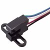
Shouldn't be too hard. All I have to do is shrink it down and add a missing tooth. I am in pretty good with the machine shop here where I'm stationed, and they said they will do it for a soda. It will all fit in the stock CPS unit as well. For the optical portion, I will be using this...
HOA2005-001.jpg
What do you think? I should have much lower noise and it should trigger from any rpm.:icon_bigg