In need a bit of help.

Clint

AzSupras
Apr 4, 2005
1,463
7
38
40
Mesa, Arizona, United States
I am in need of help I searched but I couldn’t find any information on the "wire tuck" threw the driver side firewall.

I am looking for pictures of where the hole needs to be drilled on the firewall and also the pin outs for the ma70 body connectors and the jza70 body connectors and how long they need to be extended.

I noticed that 1jz-gte.us is out of commission so the information on that site is not available anymore. I know that Aaron and Jose both started doing this "harness tuck" I want to go this route because I don’t want to extend my whole harness.

If anybody could chime in like Aaron or Jose or anybody else who could be helpful that would be awesome :).

Thanks everybody.
 

AF1JZ

Almost civilian status...
Jun 26, 2006
3,109
0
0
Fredericksburg, VA
I think it's making the speedo cable hole bigger and passing it through there. You'll still have to get a field harness for the other connectors that aren't going to the ECU. Also, the ECU will be underneath the drivers side dash panels.
 

Clint

AzSupras
Apr 4, 2005
1,463
7
38
40
Mesa, Arizona, United States
AF1JZ said:
I think it's making the speedo cable hole bigger and passing it through there. You'll still have to get a field harness for the other connectors that aren't going to the ECU. Also, the ECU will be underneath the drivers side dash panels.

Well doesn’t the throttle cable half to be bolted down on the firewall?

Also does anybody have the diagram for the body connectors/ wiring harness from the jza70 and the ma70?
 

JonoTurbo

Going for broke
Mar 30, 2005
670
0
0
40
CT
You need at 2.5" hole saw as mike said. Look at the firewall below the speedo cable hole. There is a break hardline running across this area and it has a bracket bolted down with a single bolt. Below this bracket is an open area in the firewall, the way I do the tuck is to drill the hole right here centered in line with the bolt above it. You can also go through the speedo hole, but I recommend against it. Somewhere out there in the SM build section there is a picture of this.

As far as the wiring goes, this method requires that you mount the ECU in the stock location but with the connectors facing toward the drivers side. Then there are 30-some odd dash wires(or less depending on options) that need to be extended 16". Unfortunately I don't have helpful diagrams at the moment, but I am working on some new ones that I will post up to replace the ones that were on Rick's site.
 

Yotaholic

New Member
Apr 2, 2007
110
0
0
Nfld.Canada
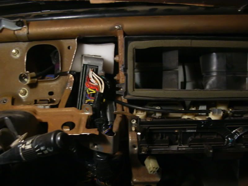
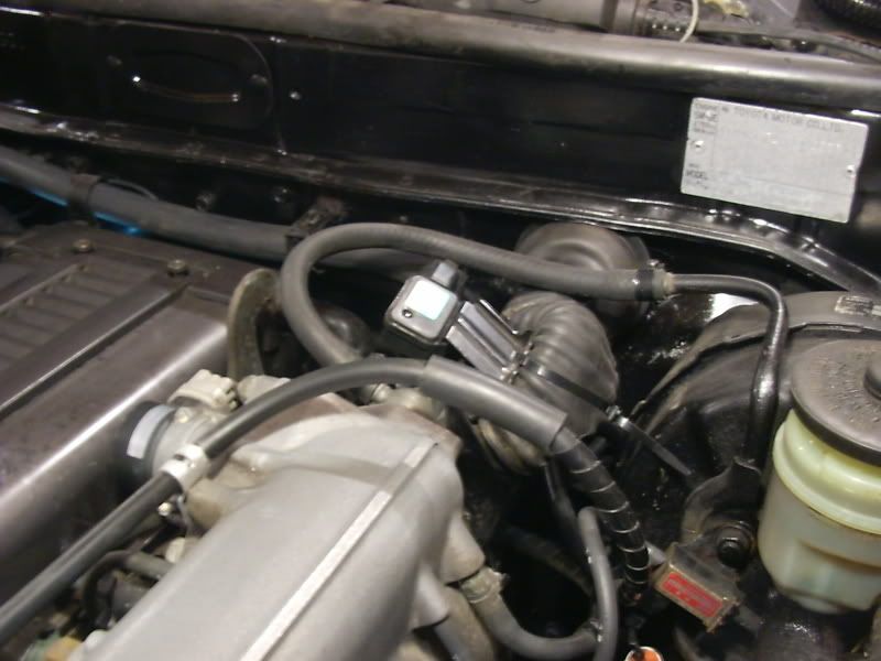
Just to throw another option at ya , I decided to not extend the harness at all and now you can tap the few wires you need on the drivers side :icon_bigg . Nice and clean and no worries about bad solder joins or broken wires down the road. Every join you make is one more to worry about was my theory especially if something suddenly goes wrong .

Yes it's a MKII but the idea and the space behind the cluster is roughly the same so it's something to consider. Hope the MKII doesn't offend anyone :icon_conf

p720409_1.jpg


yes zip tie on the map sensor at the time....

p720409_2.jpg
 
Last edited:

Clint

AzSupras
Apr 4, 2005
1,463
7
38
40
Mesa, Arizona, United States
Does anybody know how the engine harness goes back on the motor? lol I feel like a tard I don’t remember how it goes one if anybody has any pictures that would help thanks!