
A relay is just a switch which is usually used to allow a small current to close a switch that allows a larger current to flow. For my case I needed a relay that would allow a wire (to my electric aerial) to switch to a certain two wires to go up then break the connection to go down
There are two properties of a relay that you need to know:
1. The number of 'poles' refers to the number of current paths - think of this as the number of switches within the relay (So you could switch more than one set of wires togehter if need be)
2. The number of 'throws' (Terminology is "single throw" then "double throw" but then it becomes "3 way", "4 way" etc) - this is the number of different routes current can take - think of this as the number of positions for each switch
So in my example I have two wires that I need to switch together So I want ONE switch which has ONE current path - a single pole, single throw relay.
Although it has one current path, that doesn't mean it is always switched on it just means that there is only one position for the switch to go to when the relay is switched on i.e. it is either on or off.
The relay actuates (switches) by exciting a coil with a voltage, all this means is that we need to give it 12 volts (Make sure you get a 12 volt relay for working with our cars) and a ground supply to switch it. In my case I wanted the head unit of my stereo to actuate the switch so I hooked the remote wire (Which is blue on ISO connectors for your head unit) to the 12V feed on the relay and grounded the relay using one of my spare grounds in the wiring loom for the stereo.
Just to confuse matters I'm actually using a dual pole single throw relay (Which means there are two switches which have one position each i.e. on/off). I was intending to wire both wires independently but found that pairing them together did exactly what I needed.
Right, so we have :
a) 12 volt feed switched on by the head unit
b) Ground connection
c) A wire which goes to the antenna (Blue/yellow)
d) Wire which is used to make the antenna go up and down (Blue/pink tied together with red/black)
e) A spare unused pin
This (blurry) picture shows the relay with its 5 pins :
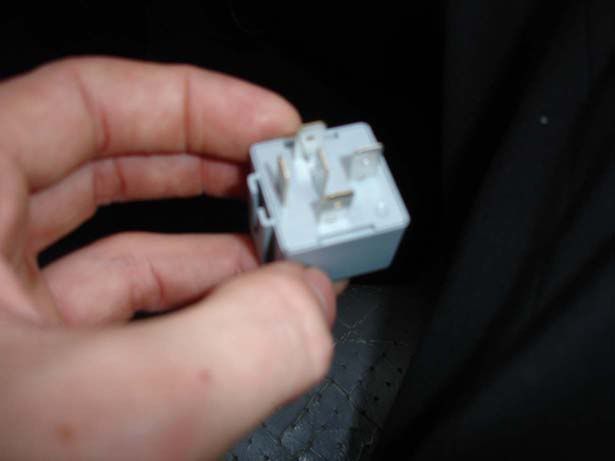
You can see that they just use normal spade connectors.
On your relay you will have a number next to each spade connetor and hopefully a diagram on the top to tell you how to wire it. I will explain the one I got and hopefully you should be able to use this to help on any relays you get
The circuit diagram on the top of the relay will show you what each wire does and tell you what number spade connector it refers to on the base of the relay. On mine I had the following :
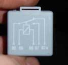
30 is the wire to the antenna. You can tell this because it connects to a switch with two different possible connections (87a or 87). The picture shows the switch is 'normally open' for 87 and 'normally closed' for 87a. This means that when you supply the 12 volt feed, 87 will connect to 30 (our antenna) so this wants to be the wire to make the antenna go up. When we remove 12V the switch is broken and the antenna drops.
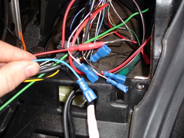
So they are the important wires, all we're left with is 85 and 86 which are + and - so we hook the 12V feed from the head unit to 85 and ground 86. When
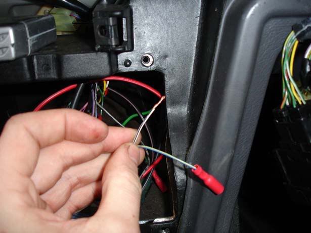
wiring in the stereo I had several ground wires and picked the white with a black stripe to ground the relay as shown below
If you can get hold of one of these crimpers it will make your life much easier
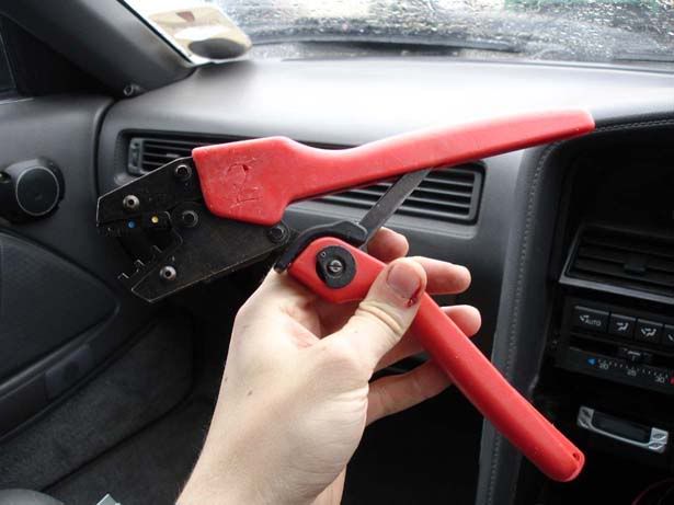
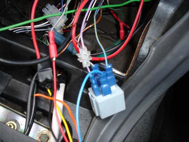
Do all four of your wires (There are five shown here because it was before I spliced two together)
The finished relay
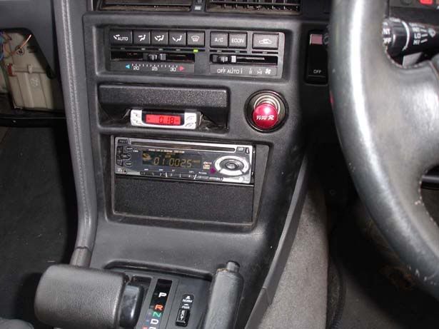
The stereo finished
I hope that helps, please let me know if anything is confusing
Oh, and for info I got my 5 pin relay with 5 spade connectors and a mounting bracket for 3 quid so they aren't expensive devices (And you can pay less than that)
There are two properties of a relay that you need to know:
1. The number of 'poles' refers to the number of current paths - think of this as the number of switches within the relay (So you could switch more than one set of wires togehter if need be)
2. The number of 'throws' (Terminology is "single throw" then "double throw" but then it becomes "3 way", "4 way" etc) - this is the number of different routes current can take - think of this as the number of positions for each switch
So in my example I have two wires that I need to switch together So I want ONE switch which has ONE current path - a single pole, single throw relay.
Although it has one current path, that doesn't mean it is always switched on it just means that there is only one position for the switch to go to when the relay is switched on i.e. it is either on or off.
The relay actuates (switches) by exciting a coil with a voltage, all this means is that we need to give it 12 volts (Make sure you get a 12 volt relay for working with our cars) and a ground supply to switch it. In my case I wanted the head unit of my stereo to actuate the switch so I hooked the remote wire (Which is blue on ISO connectors for your head unit) to the 12V feed on the relay and grounded the relay using one of my spare grounds in the wiring loom for the stereo.
Just to confuse matters I'm actually using a dual pole single throw relay (Which means there are two switches which have one position each i.e. on/off). I was intending to wire both wires independently but found that pairing them together did exactly what I needed.
Right, so we have :
a) 12 volt feed switched on by the head unit
b) Ground connection
c) A wire which goes to the antenna (Blue/yellow)
d) Wire which is used to make the antenna go up and down (Blue/pink tied together with red/black)
e) A spare unused pin
This (blurry) picture shows the relay with its 5 pins :
You can see that they just use normal spade connectors.
On your relay you will have a number next to each spade connetor and hopefully a diagram on the top to tell you how to wire it. I will explain the one I got and hopefully you should be able to use this to help on any relays you get
The circuit diagram on the top of the relay will show you what each wire does and tell you what number spade connector it refers to on the base of the relay. On mine I had the following :
30 is the wire to the antenna. You can tell this because it connects to a switch with two different possible connections (87a or 87). The picture shows the switch is 'normally open' for 87 and 'normally closed' for 87a. This means that when you supply the 12 volt feed, 87 will connect to 30 (our antenna) so this wants to be the wire to make the antenna go up. When we remove 12V the switch is broken and the antenna drops.
So they are the important wires, all we're left with is 85 and 86 which are + and - so we hook the 12V feed from the head unit to 85 and ground 86. When
wiring in the stereo I had several ground wires and picked the white with a black stripe to ground the relay as shown below
If you can get hold of one of these crimpers it will make your life much easier
Do all four of your wires (There are five shown here because it was before I spliced two together)
The finished relay
The stereo finished
I hope that helps, please let me know if anything is confusing
Oh, and for info I got my 5 pin relay with 5 spade connectors and a mounting bracket for 3 quid so they aren't expensive devices (And you can pay less than that)