All: I'm attempting to put this together with the idea that once it is corrected and complete, it can be stickied for general reference. Please make any corrections and input as you see fit, all input is greatly appreciated! Thanks!
_________________________________________________________________________
Current Chassis: 1989 Turbo MA70
Current Motor: 1JZ-GTE (from JZA70 Supra)
Goal(s):
1) Determine which alternator wire(s) need to be extended and which need to be omitted for a 1JZ-GTE swap into a late 89 MA70 chassis.
2) Determine the best method for doing so.
3) Determine lengths of wire, gauge, and connectors required to complete said task.
Photos:
Pic A:

Pic B:

Pic C:

Assumptions:
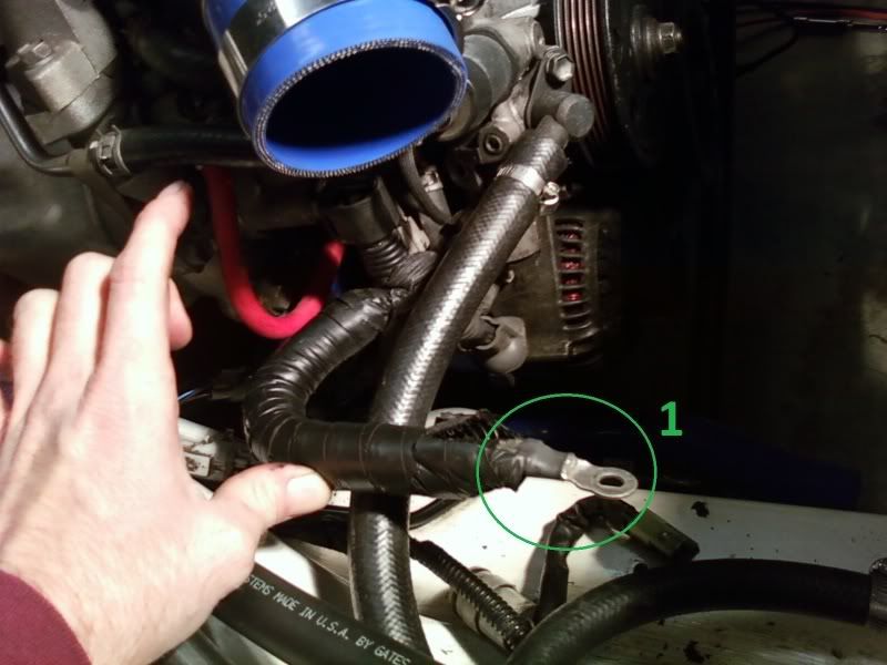
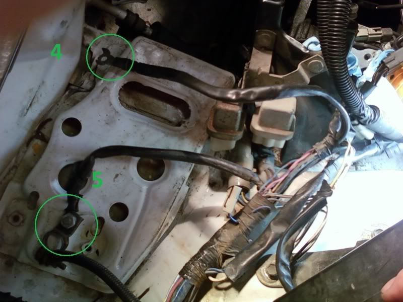
1) The wire labeled #1 needs to be extended to meet wire #4, or #1 is removed completely and #4 is extended to meet the alternator. Wire #1 and wire #4 are actually composed of two wires (assuming 8 AWG) running parallel to each other. I could either continue the use of two parallel sections of 8 AWG or use one single, larger gauge piece, such as 4 AWG. New wire length required will be 6 feet of a single, larger wire gauge, or 12 feet using two parallel, smaller gauge sections. A new connection (eye) goes onto the end of the wire(s) that will connect to the alternator. The other end(s) will be soldered and heat shrinked onto the cut #4 wire. The wire should be covered in a protective sheath and can be routed above the radiator/condensor.
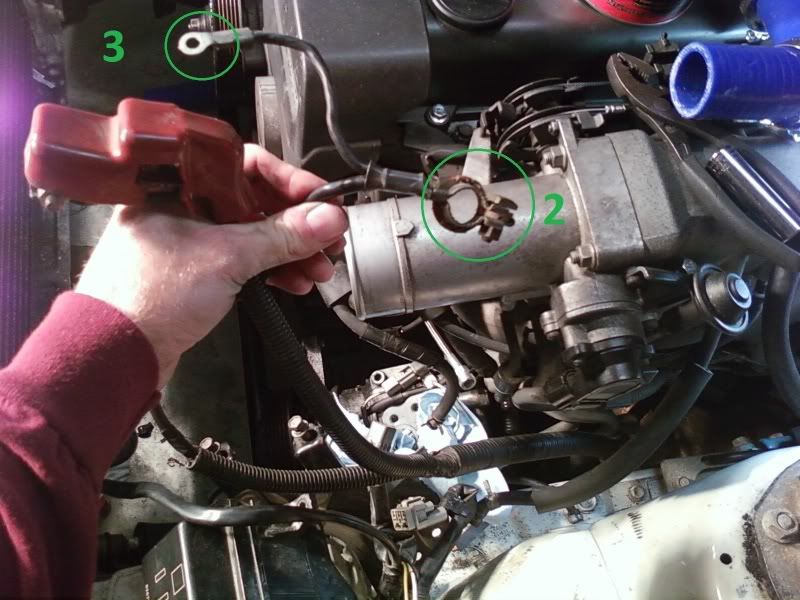
2) The wire set in Pic B leads to the starter. It consists of the positive and negative wires that will connect directly to the battery. The negative wire splits into two wires that I’ve labeled #2 and #3. #2 will connect directly to the negative battery terminal while wire three is a ground. The ground is connected to an available location on the chassis.
3) Wire #5 is on the existing (MA70 for 7M-GTE) body harness. The nut is removed from #5 and the wire is connected to the positive lead (not numbered) coming from the starter shown in Pic B. The other sheathed wire that is shown connected to #5 is for the stereo. This is removed from the terminal shown in Pic C and reconnected to the positive terminal shown in Pic B.
4) 3 wires from the MA70 alternator connector “D” get spliced into ports 10, 11, and 12 on a JZA70 EA2 connector. (pics to be added).
_________________________________________________________________________
Current Chassis: 1989 Turbo MA70
Current Motor: 1JZ-GTE (from JZA70 Supra)
Goal(s):
1) Determine which alternator wire(s) need to be extended and which need to be omitted for a 1JZ-GTE swap into a late 89 MA70 chassis.
2) Determine the best method for doing so.
3) Determine lengths of wire, gauge, and connectors required to complete said task.
Photos:
Pic A:

Pic B:

Pic C:

Assumptions:
1) The wire labeled #1 needs to be extended to meet wire #4, or #1 is removed completely and #4 is extended to meet the alternator. Wire #1 and wire #4 are actually composed of two wires (assuming 8 AWG) running parallel to each other. I could either continue the use of two parallel sections of 8 AWG or use one single, larger gauge piece, such as 4 AWG. New wire length required will be 6 feet of a single, larger wire gauge, or 12 feet using two parallel, smaller gauge sections. A new connection (eye) goes onto the end of the wire(s) that will connect to the alternator. The other end(s) will be soldered and heat shrinked onto the cut #4 wire. The wire should be covered in a protective sheath and can be routed above the radiator/condensor.
2) The wire set in Pic B leads to the starter. It consists of the positive and negative wires that will connect directly to the battery. The negative wire splits into two wires that I’ve labeled #2 and #3. #2 will connect directly to the negative battery terminal while wire three is a ground. The ground is connected to an available location on the chassis.
3) Wire #5 is on the existing (MA70 for 7M-GTE) body harness. The nut is removed from #5 and the wire is connected to the positive lead (not numbered) coming from the starter shown in Pic B. The other sheathed wire that is shown connected to #5 is for the stereo. This is removed from the terminal shown in Pic C and reconnected to the positive terminal shown in Pic B.
4) 3 wires from the MA70 alternator connector “D” get spliced into ports 10, 11, and 12 on a JZA70 EA2 connector. (pics to be added).
Last edited:

